Categories
Has Own Video WW2 US Prototypes

Wallace Leaping Tank

United States of America (1942-1945)
Walking Pillbox – None Built

If someone tried to define the term ‘tank’ as a military vehicle, they generally would agree on the need for a turret, armor, and tracks. Whilst there are exceptions to each of these to one degree or another, the only real unifying point across definitions is the use of armor and this raises interesting possibilities, especially for Henry Wallace of Freeport, New York, USA. In 1942, Henry Wallace expanded the idea of what a tank can be to a vehicle with no tracks at all. In fact, Wallace did not even go for wheels for some wheeled tank/armored car, nor did he go the full way towards a legged machine. Instead, Wallace went for perhaps the most unusual method of transportation possible, a vehicle that walked on one leg, pushing what could be named as a tank to a new extreme.

The Man

The patent for this odd design came from Henry W. Wallace of Freeport, New York State, USA. He should not be confused with the US Secretary of State for Agriculture of the time with the same name. Freeport, New York, is not a large city but, as of 1940, there were just over twenty thousand people living there according to US Census Data. The only other patent from this man was filed in October 1940 and was for a flexible pen in the shape of a snake wrapped around the wrist. With a relatively common name and few other details to go off, there is insufficient information to be able to reliably identify the designer at this time.

Concept

There are inherent problems in a tank design that involve compromises. Whether operating on wheels or tracks, movement is limited to the direction the vehicle faces and a change in direction involves turning or reversing. Protection for the vehicle is concentrated forwards to protect from fire from the front, as it would be too heavy and impractical to add equivalent protection to the sides and especially to the rear. Thus, a conventionally laid out combat vehicle is more vulnerable from the sides and rear than the front. Any turning or change in direction by the vehicle might expose that weakness to an enemy. A vehicle on which all sides are equally armored does not have to worry about the direction of an enemy attack or even turn to face it.

The same is true for armament. With a vehicle carrying a turret armament, it has to be turned to target a specific threat, and, once more, the maximum of protection faces the enemy threat. Armor protection, as both weight and bulk have to be shared between the turret and hull, provides a challenge for a designer as to where to use the armor for optimal value.

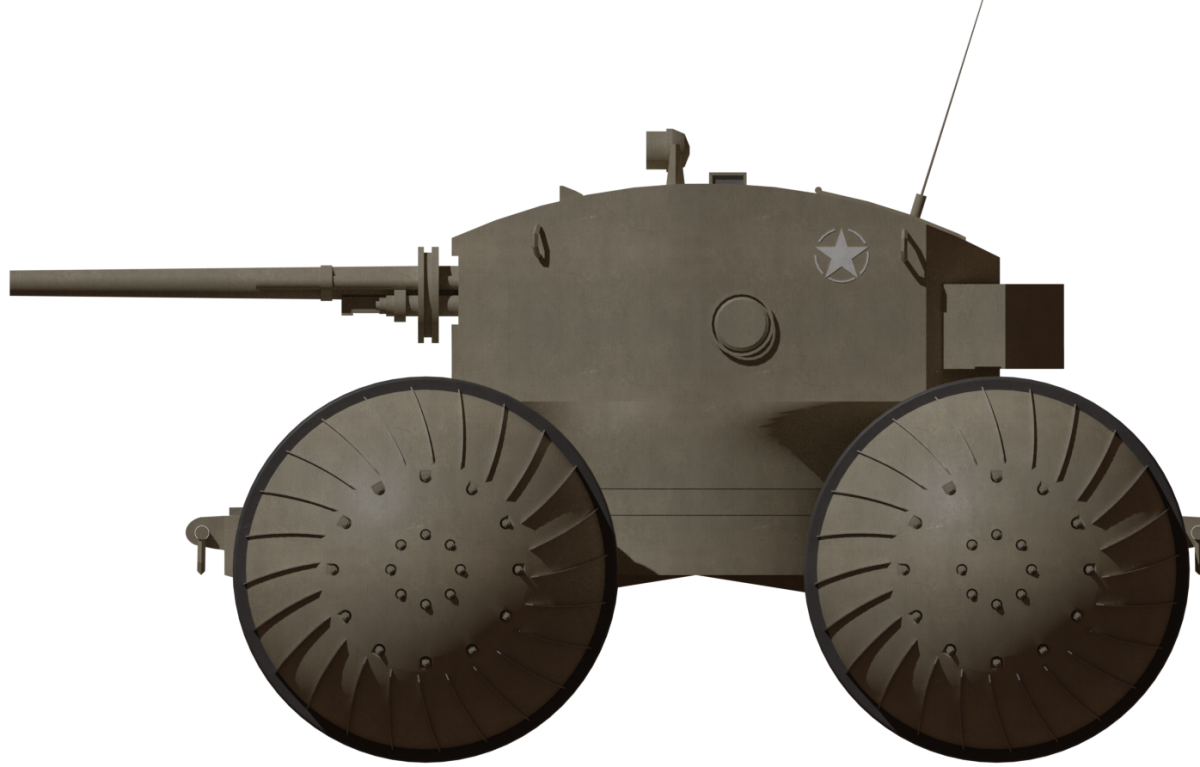
With those two primary considerations in mind, the conventional vehicle cannot deliver equal protection and firepower all round – for Wallace, the solution was effectively a simple one. Create a vehicle that was symmetrical in defensive capabilities and offensive alike, and this meant a circular body. This body would make the tank especially valuable in a defensive situation, where it could simply ‘sit’ as a bunker to guard or control an area and then, when the job was done, move on.

The propulsion of such a vehicle could not rely upon tracks or wheels, as it would not be able to change direction quickly enough in the mind of Wallace. Instead, he opted for a single leg which was located in the center of the doughnut-shaped machine. With this, he felt, the tank would be able to “oscillate” to move, with all-round gun positions guaranteeing that firepower constantly faced the enemy. Thus, the vehicle could advance, retreat or move sideways without regard to enemy position or flanking attacks.

Layout

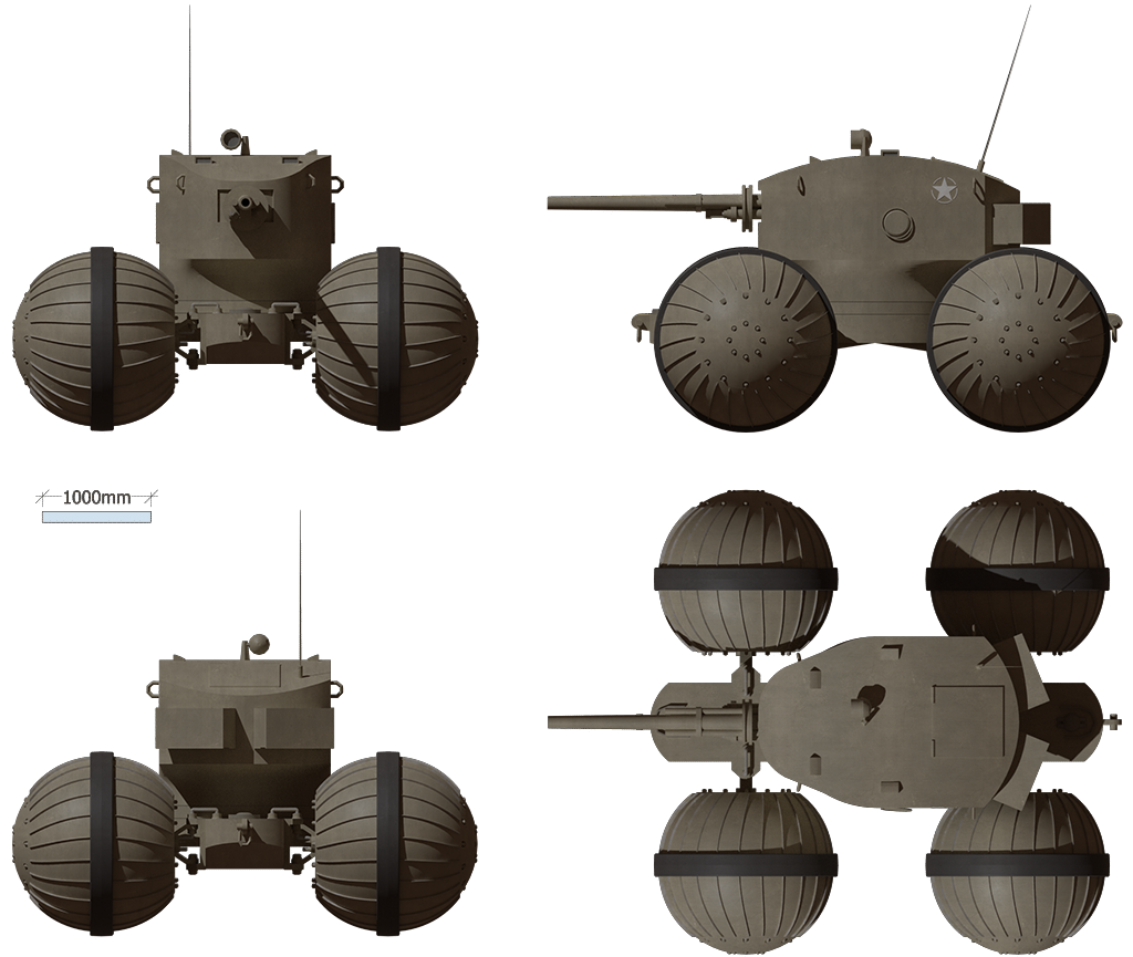
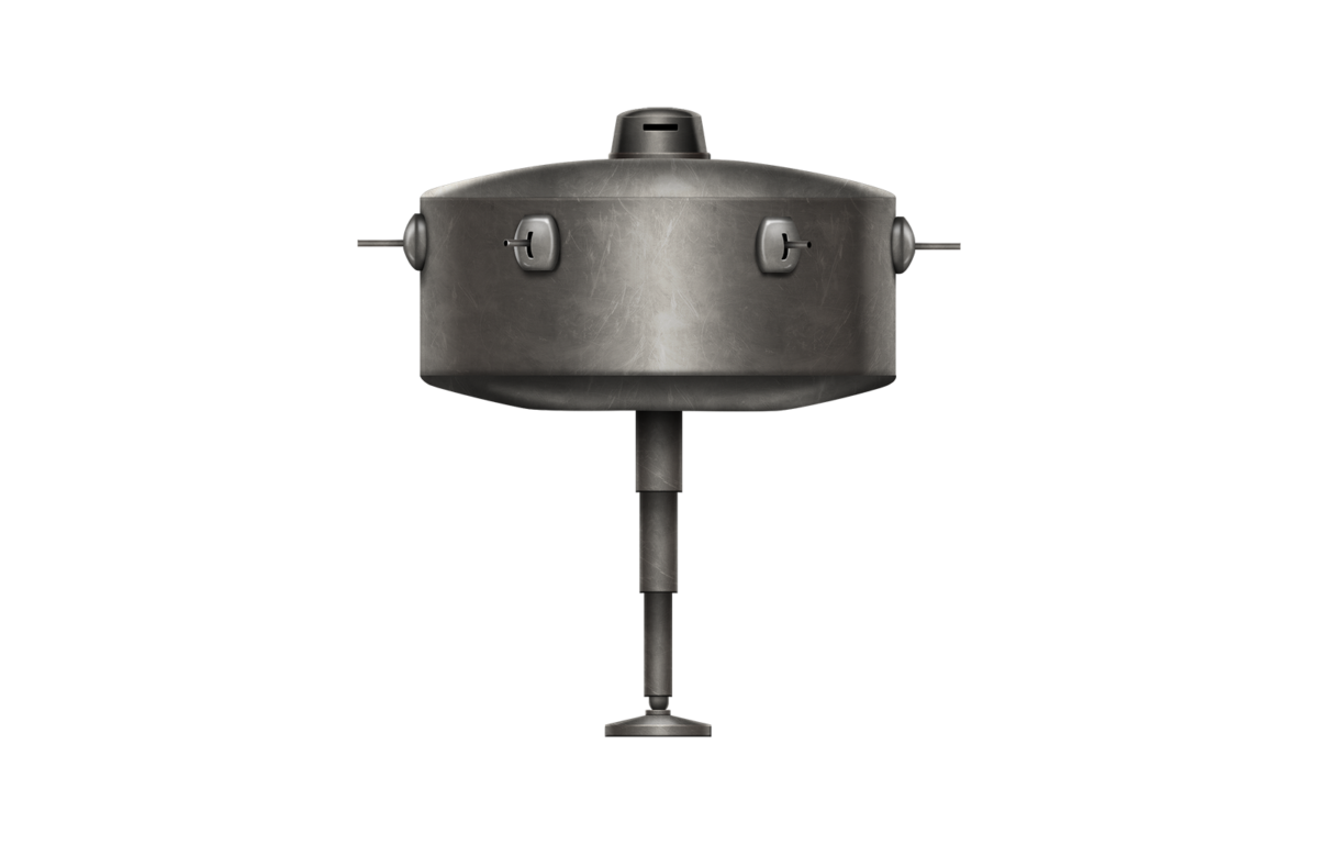
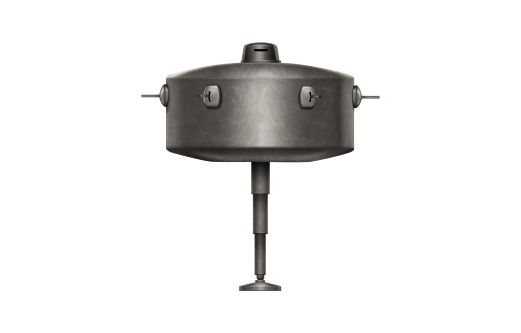
With a doughnut-shaped body resembling a pressure cooker or saucepan with a lid, the machine was certainly odd. The ‘handle’ of the lid was a small cabin that could be rotated in any direction and in which sat the driver of the machine, with a view slit for observation.

The driver’s cabin was located on top of the machine and could rotate within the machine.
Source: US Patent US2371368

The rest of the machine was circular, with 6 gun positions located at 60 degrees from each other. Each position had a field of fire of up to 45 degrees to each side, which managed to create small blindspots immediately alongside the vehicle between the guns.

Seen from above, the vehicle has no ‘weak’ side, as it is circular, with weapons equally spread around the circumference.
Source: Modified from US Patent US2371368 by Author

The smooth exterior of the vehicle was broken up by the 6 gun positions, but there would be no sign of the propulsion leg from the outside when the vehicle was ‘sat’ down as a pillbox. The leg itself resided in an octagonal area within the floor of the tank, with its gearing and hydraulic actuators around it to control its position and direction. The extension of the leg, however, was not done hydraulically but using compressed air or, as suggested by Wallace, by means of an explosive expansion of gas. This might have seemed like a good idea for a patent application, but was utterly preposterous for even this rather silly design. The automotive power was to come from a two-stroke fuel-injected diesel engine of an unspecified type. In a lengthy explanation of how the whole system was meant to work, Wallace explained that this explosive method was to work by releasing fuel into the top of the hollow extensible cylinders which formed the leg and that, with a single detonation of a cartridge into this cylinder, the explosive gases from this detonation would rapidly propel the vehicle upwards to get out of trouble or leap into action. Quite what effect this bounding kangaroo leap would have on the occupants is not explained and perhaps was never even considered as a possible issue or concern.

The octagonal central space is occupied by the propulsion leg and associated hydraulic pistons for controlling its position and movement. The driver sat directly over this central position.
Source: US Patent US2371368. Note this image has been digitally cleaned by the author.
Cross-section elevation of Wallace’s design showing the large central area for the propulsive leg and driver’s cab over the top of it.
Source: US Patent US2371368. Source: US Patent US2371368

The rest of the internal arrangement within the machine was relatively straightforward. Between the outer walls, with those 6 gun positions, was a raised fighting platform under which ran a lot of the mechanical equipment (such as pumps) to run the machine. The outer skin of the machine was supported at the top and bottom by supporting beams. Despite the size of the machine and the number of men within it, just one hatch is shown in the patent drawing, in the rotating cabin for the driver at the top.

In terms of crew, even assuming just one man per gun (x 6), a driver, and a commander would mean not less than 8 men to reasonably crew this vehicle.

Propulsion

Whilst there have been designs for walking machines before, they usually relied upon continual support by their legs even when not in motion. More than that, they also had to depend on at least 2 legs for bipedal stability or more in motion. Wallace eschewed such ideas or any concept of motion short of brachiation from nature and went instead for a system using one leg. It is obviously not possible to walk on one leg without a hopping motion, but the design did not produce some giant pogo stick type of movement. It instead had an unusual undulating step where the second ‘foot’ would be the vehicle itself.

Consisting of a giant doughnut shape, with the single leg occupying the central recess in the bottom, at rest, the vehicle sat on the ground as a giant round fort or pillbox. During this phase, the leg could move forwards to a position in the direction of movement and then lift the whole vehicle off the ground, bringing it upwards and in the direction of travel. Now having moved a short distance ahead or in any direction, the leg would collapse slowly bringing the vehicle back to rest on the ground. The process would then repeat for as long as may be needed to move from location A to B. At all times whilst sitting on the ground, the leg was completely enclosed by the body and the vehicle provided both maximum firepower and maximum protection in all dimensions simultaneously. Using four large wheels, one on each side of the leg, and an element of rotation within the housing for it, the leg could be prepositioned in any direction in anticipation of a move that would be unknown to anyone outside the machine by observing it.

There are, however, serious problems with this method of motion, not least of which are ground pressure, balance, and speed.

Firstly, with the entire weight of the vehicle concentrated onto just a single point of contact with the ground. As the leg extended hydraulically into the ground to raise the body, it would sink into anything other than a good hard surface. The result would potentially be the leg impaling the ground to an extent that it might not be easily removed. This would be the military equivalent of trying to walk on a beach in high heels. If this sinking happened when the body was off the ground, the result could be disastrous, as moving a point of balance beyond the lip of the foot would result in the machine flailing over.

This brings up the second point of balance. Not only could the machine potentially tip if the ground shifted or leg sank when moving, but this would be magnified as a problem moving on anything other than a flat surface. Whilst the foot itself had a semi-flexible coupling in the manner of an ‘ankle’ connecting it to the base of the leg, the foot allowed for a limited degree of flexibility. Measurements of the vehicle would indicate that it would become unstable past 10 degrees of any slope. This would render the vehicle unable to operate on anything other than ideal flat terrain. Wallace sought to correct this rather obvious deficiency with his idea by stating that it was to use a gyroscopic stabilization device located around the center of gravity and consisting of two oppositional gyroscopes.

Even allowing for the body to pivot and remain horizontal, once the vehicle gets past 10 degrees from vertical, it is unstable. Source: US Patent US2371368 digitally modified by the author.

The final major problem with the practicalities of the mean of motion for the vehicle is speed. Movement in the chosen direction is limited by the amount of movement available to the foot at the point when the body of the vehicle is on the ground. Moving the foot in the desired direction whilst on the ground (1), as the hydraulics push on the foot, the body gradually lifts off the ground and is righted to a new forward position (2) until reaching full height (3). The tank can remain at any elevation between ground level and (3) for combat, although this would expose the leg to enemy fire. Return to the ground starts from the elevated position (4) down vertically (5) to the new resting position (6), a short distance from point (1). To continue the motion, the leg is moved to the new forward position (7) and the vehicle rises (8) to a new elevation (9) and so on.

Movement through phases of elevation. Source: Author

One step beyond this slow move-lift-lower means of motion, Wallace drew an even more fanciful one. Here, the leg would do far more than even those rather absurd methods of movement, showing the tank literally jumping.

Even had the idea been a practical one, Wallace’s ridiculous concept for tank movement ensured that not only would the vehicle be very easy to see leaping above any cover but also that any crew inside would be in no fit shape to fight at the end of it.
Source: US2371368

This slow move-lift-lower process could be sped up to a ‘dragging’ speed whereby only enough pressure need be applied to the foot to raise the body from the ground far enough that the hydraulics for the leg movement could drag it forwards and then return to the body to rest as the foot moves again. It is surely this method that would have been the only practical way of moving the vehicle, although practical is not really applicable to such an implausible design.

‘Walking’ by dragging the lidded-saucepan-shaped vehicle would have been a bumpy and slow affair.
Source: Author

Wallace made no mention or estimate of the speed of this system of propulsion, but it was clearly not possible to combine a rapid bounding from the machine with a chance of the crew being in a fighting condition, even assuming the system had worked. The easiest, simplest, safest form of motion, the dragging method, would perhaps at best manage walking pace on a good surface.

Armor

As with many other features of this vehicle, little information can be discerned on which to judge the level of protection provided. No information is provided other than to say that protection was implied as being equal in all directions. From the approximate scale of the vehicle, the size of the seat, and space for the crew, the drawing would appear to indicate armor would have to have been metal (presumably steel) and not much more than bulletproof in thickness.

Armament

With 6 evenly distributed guns around the outside, it is unclear what sort of firepower Wallace had in mind. An enemy could be engaged at best by just two of the guns at any one time, leaving ⅔ of the firepower idle. Wallace could simply have had a rotating turret with a single large gun or multiple gun mountings, which would have obviated the need for so many crew and guns. Instead, unless the vehicle was totally surrounded, then all of the firepower could never be used at the same time and none of it when moving.

Conclusion

Weakly protected for a static pillbox, poorly protected for such a visible tank, and oddly armored for a fighting vehicle, the design was particularly bad when it came to motion. The single-leg concept, as drawn, was preposterous and unlikely to work even on a flat and hard surface, let alone a modest slope or wet ground. There, this tank would display the mobility of a lawn dart when moving and a house brick at other times, with less potential than either.

What Wallace was trying to secure as intellectual property with this design is clearly the single springing leg concept and a tank of equal protection and firepower. What he actually designed was perhaps one of the least practical, workable, or sensible systems of vehicular motion imaginable.

Trying to imagine what possible use this vehicle might have had to the US military or Allies in 1942, when it was submitted, is even less clear. Today, it can be seen as just one of those ideas from a well-meaning public eager to engage in and/or profit from the war by producing war-winning weapons and ideas. Sadly for Wallace, this was not one of them.

The Wallace Leaping Tank is probably the oddest military vehicle ever proposed. Or, at least, the oddest we ever found. Illustration by Yuvnashva Sharma.

Sources

US Patent US2371368 Vehicle, filed 16th October 1942, granted 13th March 1945
US Patent US2266942 Bracelet, field 24th October 1940, granted 23rd December 1941
US Decennial Census data https://www.census.gov/programs-surveys/decennial-census.html

Categories
WW2 US Prototypes

Armored Utility Vehicle T13 and Cargo Carrier T33

United States of America (1944-1945)
Utility Vehicle – Prototypes Only

The T33 Cargo Carrier and T13 Armored Utility Vehicle were designed in the United States of America during the Second World War. The T13 and T33 occupy a space in development as transition vehicles in the sense that almost everything Armored Personnel Carrier related that comes before the T13 and T33 was adopted from other designs originally intended as artillery tractors, half-tracks, tanks or, mortar carriers. Although neither vehicle was adopted for mass production, much like those that preceded them, they set the standard and bar for future APCs on what was expected and needed of the vehicle.

Initial Development

The T33 Cargo Carrier and T13 Armored Utility Vehicle (the name was changed to this from Armoured Tracked Carrier) were first mentioned in August 1944 in the British Army Staff (AFV) Situation Report Number 25 from August 18th 1944. At the time, the Armored Board and Armored Centre were interested in a design of an Armored Tracked Carrier, eventually called T13, based upon the M24 Light Tank components. The proposal was for the driver and engine room to be at the front, followed by a body which would be capable of carrying a 13,000 lb (5,900 kg) payload. Its dimensions would enable 9 men to be carried in the body with an additional 2 in the driving compartment.
The armor over the hull of the chassis would be 1” (25.4 mm), whilst the body would be ½” (12.7 mm). The total weight of the vehicle was estimated at 40,000 lbs (18,143.69 kg). Such a Carrier was considered to be particularly desirable for acting as a tender for ammunition and fuel for the M24 Light Tank, which only carried 48 rounds, or as a personnel carrier, or command vehicle in theaters such as China, where the absence of roads placed a premium on tracked vehicles. As of August 18th, 1944, “a layout drawing only has been produced and support for the proposal is now being canvased.”
There were no fully tracked armored personnel carriers being produced anywhere in the world since the Mark IX tank of World War One and APCs based upon the Soviet T-26 in the early 1930s. Walking, trains, trucks, and increasingly, half-tracks were the primary ways to move troops. The Tank Policy for 1945, which was published in July 1944, laid out the main focus for the coming year in the European Theater of Operations (ETO), that focus being on Tanks carrying a minimum of 70 rounds of ammunition. Water stowage for these rounds to reduce the chances of fire was acceptable so long as no less than 70 rounds were carried. Ground pressure was not to exceed 10 psi (0.70307 kg/cm2) and tank design was to be split into two types, light armor and high mobility, and heavy armor and infantry support. The end result of the requirements from July 1944 was that the M4A3 Medium Tank and M24 Light Tank fitted the lighter requirements well. At the same time, while the T25E1 Medium Tank was considered, it was thought that it would negatively impact the production of the M4A3 Medium Tank and M24 Light Tank and, if it was introduced alongside the two tanks, it would not arrive in enough quantity to have any impact. The heavy role was to be filled by the T26E1 Heavy Tank, and both the light and heavy tank roles were supposed to be able to mount the 90 mm Gun and the 105 mm Howitzer.
In addition to the Tank Policy, the Army was in need of more tractors to haul towed guns of various calibers due to production of the M4, M5, and M6 Tractors (as well as Tractor Trucks) not being able to keep up with demand and the increasing production of towed gun carriages. The idea to convert M24 chassis into both Cargo Tractors and Armored Utility Vehicles was both sound and nothing new, as the idea had been previously considered and declined.

October 1944

By October of 1944, it had been expressed in overseas theaters of operation, that a definite need existed for a General Purpose Tracked Cargo Carrier with low unit track pressure (PSI) and effective cross-country performance over difficult terrain. To meet this requirement, Ordinance prepared a design for a new carrier with a 7-ton cargo (6.4-tonne) capacity identified as the T33 Cargo Carrier. The vehicle was to be built from standard M24 Light Tank components, be unarmored, have a crew of two, and a .50 cal machine gun for A.A. work manned by the assistant driver. The unit track pressure was to be 6 psi (0.42 kg/cm2). Six pilot vehicles were authorized, but as of October 1944, no manufacturing facility had been located. Also recommended for official investigation was the previously mentioned armored tracked carrier based off the T33, the T13, now called a Personnel Carrier which had been previously reported on back in August of 1944[4].


Images of the Cargo Carrier T33 from October 1944. Source: British Army Staff (AFV) Situation Report Number 27 October 18th 1944

In November of 1944, the T33 Cargo Carrier became better described as 24,000 lbs (10.9-tonnes) (less crew, stowage and fuel) and 39,000 lbs (17.7-tonnes kg) combat laden in a cab over engine design at the front of the chassis.
The T13 also got official recognition as the T13 Armored Utility Vehicle in which the truck cab body of the T33 was replaced with an armored body ½” (12.7 mm) thick on the front, ½” (12.7 mm) thick on the side and 3/8” (9.5 mm) thick on the roof. The roof was lifted by means of mechanical jacks which raised it to any required position up to 6 ft (1.83 m) above the floor. The driver’s compartment accommodated the driver and co-driver with a ring-mounted .50 caliber machine gun over the co-driver. The main body was designed to accommodate 16 men in four rows of four leaving a small central aisle. This vehicle was estimated to weigh 31,000 lbs (14-tonnes) (less crew, stowage and fuel) and 39,000 lbs (17.7-tonnes) combat laden with the ground pressure being 7.3 psi (0.51kg/cm2).
The base carrier design was also intended to be suitable as an a) Armored Personnel or Cargo Carrier, b) Full Track Armored Reconnaissance Vehicle, c) Gun Motor Carriage, d) Litter Carrier and e)Full Track Armored Prime Mover.
The B.A.S. Royal Artillery S.D. and T. (R.A.) Monthly Letter to the War Office(RA) for December 7th, 1944 notes that the T33 had been approved for the production of six pilot vehicles[8]. The Technical Services Armaments Letter (TSAL) for November 29th, 1944 also notes this. Curiously, the British Army Staff (AFV) Situation Report (BASSR) Number 28 for November 18th, 1944 makes no mention of the six pilots for the T13 and both the TSAL and RA reports do and both reports cite BASSR #27 from October 18th, 1944.
By February 1945 and as a result of several user criticisms, the wooden mockup for T13 Armored Utility Vehicle was undergoing modifications and was not yet complete. In addition, six prototype T13 Armored Utility Vehicles were still on order but no delivery dates had yet been established[9].


Armored Utility Vehicle as drawn in the British Army Staff (AFV) Situation Report from November 1944. Illustrated by Yuvnashva Sharma, funded by our Patreon campaign.


Drawings and scale model of the Armored Utility Vehicle T13 from November 1944. Source: British Army Staff (AFV) Situation Report Number 28 November 18th, 1944

March 1945 – All-Change, and the end of the T33

In March of 1945, everything changed for the T33 Cargo Carrier and T13 Armored Utility Vehicle. Cargo Carrier policy, as far as it affected the Armored Force and Tank Destroyer Command, appeared to the British to be focused around the T33 Cargo Carrier. The British at the time called the T33 an Armored Personnel Carrier. The discussion remained open as to if the overhead armored protection, previously mentioned back in November 1944, on the T13 was necessary as it was being contended at the time that its presence would prevent a complement of 30 men from leaving the vehicle speedily. On the other hand, it was also admitted that, with the development of the proximity fuse (VT Fuse), overhead cover was essential.
By the end of the month, the T33 Cargo Carrier was canceled in favor of the T42 Cargo Carrier/Prime Mover/Cargo Tractor. The T42 would be, at first, nearly identical to the T33 Cargo Carrier, but with the adoption of the M18’s 900-T Torquematic gearbox and the R-975-C4 radial engine as its powerplant. The T42 was also cross-adopted as a prime mover as Cargo Tractor T42 to replace the 18-ton High-Speed Tractor M4, a project that originally started in February of 1945.

The end of the T13

In April 1945, the T13 Armored Utility Vehicle, with the new powertrain adopted from the M18, was officially redesignated T16 Armored Utility Vehicle and the T13 Armored Utility Vehicle, based upon the chassis of the M24, canceled.
With the cancelation of the T33 Cargo Carrier and T13 Armored Utility Vehicle, work on another Cargo Carrier and Armored Utility Vehicle would continue on in the development of the T42(M8) Prime Mover/Cargo Tractor/Cargo Carrier and T16(M44) Armored Utility Vehicle both of which would become accepted into Standard and then Limited Standard service by the United States.

Sources

British Army Staff (AFV) Situation Report Number 25 August 18th 1944
British Army Staff (AFV) Situation Report Number 24 July 18th 1944
British Army Staff Royal Artillery Monthly Letters September 1944 Para 13 (012)
British Army Staff (AFV) Situation Report Number 27 October 18th 1944
British Army Staff (AFV) Situation Report Number 28 November 18th 1944
British Army Staff Royal Artillery Monthly Letters December 7th 1944
British Army Staff (AFV) Situation Report Number 31 February 18th 1945
British Army Staff (AFV) Situation Report Number 32 March 18th 1945
Technical Services Armaments Number 16 February 25th 1945
Technical Services Armaments Number 18 April 30th 1945
British Army Staff (AFV) Situation Report Number 33 April 18th 1945

Vehicle AUV proposal Cargo Carrier T33 AUV T13
Date August 1944 August 29th 1944 (reported on in October 1944) September 30th 1944 (reported on in November 1944)
Total weight 40,000 lbs (18,000 kg) 39,000 lbs (17,600 kg)
Empty eight 24,000 lbs (10,800 kg) 31,000 lbs (14,000 kg)
Crew 2 2 2 (likely)
Troops 9 0 16 (likely)
Total 11 2 18
Propulsion 2 Cadillac V8, 230 hp at 1400 rpms 2 Cadillac V8, 220 hp at 1400 rpms
Speed 34 mph (55 km/h) (Unsure) 35 mph (56 km/h) (Unsure)
Range 250 mi (400 km) 250 mi (400 km)
Armament M2 .50 cal machine-gun M2 .50 cal machine-gun
Elevation/depression +86 to -10 degrees +86 to -10 degrees
Fording ability 40 in (1 m) 40 in (1 m)
For information about abbreviations check the Lexical Index
Categories
WW2 US Prototypes

Pelican Project and Half-Track Amphibian Cargo Carrier T32

United States of America (1942-1944)
Amphibious Utility Vehicle – Scale Model Only

By July 1942, the US National Defense Research Committee (NDRC), while working on developing the DUKW amphibious transport, concluded that a larger amphibious vehicle would be needed. They presumably expected that the DUKW’s limited capacity of 2.3 tonnes would be inadequate during large scale landings. Testing was done on a number of converted trucks, however, it was found that wheeled vehicles with payloads over 6 tonnes faced severe problems due to the increased ground pressure and unsatisfactory traction on beaches, their most likely landing point. It was therefore decided that a new project would be started, looking at developing amphibious half-tracks. These were meant to provide forces with larger supply payloads during landings in Europe and the Pacific without the inherent problems that wheeled vehicles faced.

The GMC DUKW (“D” – year 1942, “U” – utility, “K” – all-wheel drive, “W” – twin rear axles), designed in 1941, started production at the end of 1942 and was to be the US Army’s backbone during naval landings. Source: warhistoryonline

The Pelican Project

As a result of converted trucks failing evaluation, a number of half-track designs were drawn up for the newly started Pelican Project. These ranged from payloads as little as 2 tonnes, all the way up to an ambitious 25 tonnes. Some designs, in an effort to lower ground pressure and increase traction even further, featured an extra set of front wheels. These extra wheels, if powered, could have increased off-road performance, but none of the designs with them were given any further consideration.
It is not known exactly how all these designs were judged, but the final design that came out of the project did at least see significant evaluation. As well as being the last design in the project, it was also one of the largest. Weighing an estimated 9 tonnes empty, with a 9-tonne maximum payload, the vehicle was to be 15.3 m long and 4.4 m wide, larger than any other amphibious vehicle at the time. The design was to use a Ford 400 hp V8 petrol engine powering a pair of either Kirsten-Boeing or Voith-Schneider vertical propellers, giving the vehicle a water speed of 13km/h.

Blueprint of the final design of the Pelican Project Source: Half-Track: A History of American Semi-Tracked Vehicles, by R. P. Hunnicutt
To take advantage of the large number of new M4 Sherman tanks being produced and to potentially ease the logistical burden of developing a brand new tracked vehicle, the Pelican half-track was to share its VVSS (Vertical Volute Spring Suspension) bogie design. It was to have two bogies per side, totaling four road wheels per side with a central separate return roller, as well as the same track link design as on M4.

VVSS suspension was the standard suspension design of most US armored vehicles until it was replaced on the M4 Sherman by HVSS (Horizontal Volute Spring Suspension). This surviving M4A4 can be found at the Portland D-Day Center, UK. Photo: Mark Nash
A full-width ramp at the rear of the vehicle provided access to the cargo hold which was large enough to accommodate a 6-ton 6×6 truck of any model. Unlike regular half-tracks, the 2.7m wide driver’s cab was placed at the very front of the vehicle in front of the engine. The driver was on the left and on his right would be seated the rest of the vehicle’s crew.
A number of scale models of the Pelican half-track were built and used in water tests, but the project was soon canceled and no working prototypes were built.

Half-Track Amphibian Cargo Carrier T32

In May 1944, the NDRC was requested by the Ordnance Department to once again design an amphibious half-track to assist during landing operations. One main difference with this new program, however, was that the vehicle was required to have a three quarter length track. This was similar to that of German half-tracks, instead of the much shorter two-bogie design of the earlier Pelican half-track and other US half-tracks. This design would reduce ground pressure by having significantly more track in contact with the ground and more road wheels to support to vehicle.
Sparkman & Steven, Inc., contracted by the OSRD (Office of Scientific Research and Development), drew up an initial half-track design with an empty weight of 17 tonnes, and a payload of 13.6 tonnes. At a maximum weight of 30.6 tonnes, this design greatly outweighed the earlier Pelican’s 18 total tonnes. This could be credited to the three quarter length track, but at 12.7 m in length and 3 m in width, the vehicle managed to stay significantly smaller in size.

Blueprint of the initial vehicle design. Note the sloped top edge of the hull, and the matching sloped waterline, suggesting the vehicle would be tilted back slightly when in the water. Source: Half-Track: A History of American Semi-Tracked Vehicles, by R. P. Hunnicutt
The vehicle was to be powered by the Continental R975-C4 petrol engine, coupled with the General Motors 900T Torqmatic Transmission. This combination, the same as on the M18 Hellcat, would have given the vehicle 400 hp with an estimated top speed of 48 km/h on land, and 13 km/h in water. The front two wheels were powered, and propulsion in water was provided by a pair of 711 mm (28 inch) diameter propellers underneath the rear of the cargo bed.


Scale model of the initial vehicle design. It is unclear why the model lacks the sloped top edge of the hull, the rounded bow, and the cover plate over the wheels that are present in the blueprint. It is possible these modifications were done in the time between the initial blueprint and the model being made. Source: Half-Track: A History of American Semi-Tracked Vehicles, by R. P. Hunnicutt
The tracks, being longer than those of the Pelican half-track, allowed the design to have 5 dual road wheels which were also substantially larger. The wheels were on independent torsion bars instead of VVSS bogies, giving them more vertical travel and providing a smoother ride. The tracks also differed from the earlier Pelican in that they were without return rollers, an unusual feature on US vehicles. The design of the links was the same as on the T87 105mm Howitzer Motor Carriage, an ongoing project to have an amphibious vehicle using M18 Hellcat components armed with a 105 mm howitzer, a project that ended soon after the war did.
The design was later modified to include an additional road wheel by moving the drive sprocket forward. The rear ramp was also reshaped to provide clearance when entering an LST (Landing Ship Tank), reducing its overall length to 11 m and its overall height to 3.05 m. On the 29th June 1944, the improved design was designated Half-Track Amphibian Cargo Carrier T32. It was requested that three prototypes be built for testing, but Army Service Forces denied the request and the entire project was canceled, just over one month after the project was started.

The revised design that was submitted for prototype testing designated T32. Source: Half-Track: A History of American Semi-Tracked Vehicles, by R. P. Hunnicutt


The ‘Pelican Project’ amphibious Half-Track.


Early version of the Half-Track Amphibian Cargo Carrier T32.


Later version of the T32.

These illustrations were produced by this article’s author, Mr. C. Ryan, and were funded by our Patreon Campaign.


Conclusion

While the Pelican design, had it been built, might have suffered to a degree because of its small ground contact area for its weight, both the Pelican and the T32 seem to have been reasonable designs for their requirements. Ultimately, the sheer number of DUKWs being produced from late-1942 onwards outmatched any potential production numbers of the two vehicles, making them largely redundant apart from their valuable ability to bring regular trucks and other large vehicles to shore.
The failure of both projects did not end the US’ interest in large amphibious cargo vehicles however, as they would go on to attempt others after the war. One such vehicle was the capable 7.3-tonne, 8-wheeled XM157 Drake in 1956, which did succeed at reaching the prototype stage. It failed to reach production, however, as the army’s interest became focused entirely on the far larger LARC-LX for its amphibious heavy cargo needs. A 4-wheeled vehicle with a 54-tonne payload, it would go on to serve in the Vietnam War and stay in service until 2001.
Dimensions (L-W-H)15.3 x 4.4 x 3.94 meters

Specifications (Pelican)

Total weight, battle-ready 9 tonnes approx.
Propulsion Ford 400 hp V8
Speed (water) 13 km/h

Dimensions (L-W-H)11 m – 12.7 x 3 x 3.05 – 3.34 meters

Specifications (T32)

Total weight, battle-ready 17 tonnes approx.
Propulsion Continental 400 hp R975-C4
Speed Est. 48km/h (land), 13km/h (water)
Payload 13.6 tonnes, several dozen passengers, or a single 6-ton 6×6 truck

Sources

R. P Hunnicutt, Half-Track: A History of American Semi-Tracked Vehicles, Presidio Press

Categories
WW2 US Prototypes

Williams’ Amphibious Vehicle

United States of America (1942)
Amphibious Armored Vehicle – None Built

Nothing spurs invention like war they say, and this is very true for Allison Williams. On the 30th December 1942, Allison Williams, from Yazoo City, Mississippi, filed a patent for a design of one of the most unusual armored cars of World War Two.
The design was created with the intention of providing “amphibian vehicles of high maneuverability adapted to attack and destroy a military tank and provided with a plurality of independent self-contained power units for driving the same”
There are three elements therefore to the design. The amphibian nature of the vehicle, the anti-tank nature of the design and, finally, the drive system.

Robert ‘Bob’ Semple (21 October 1873 – 31 January 1955)Colonel Allison Ridley Williams (1891-1966). Photo: Nashvillekit via findagrave.com

The Designer

Colonel Allison Ridley Williams (1891-1966) was born in Benton, Mississippi on 10th August 1891. He did not limit himself to just this amphibian vehicle design. He was already known as an inventor specializing in electrical control systems in the 1930s with patents filed for various steering and braking system and was referenced in Popular Science Magazine in 1939 for an electrical device controlling braking when turning. During the war, he designed not only this vehicle, but also two more successful designs for mine clearance equipment in 1944. Post-war, he continued his electrical work with patents on electric brake control for vehicles and aircraft until 1960. He is referenced in most patents as living in Yazoo from 1930s until the late 1940s after which he moved to Vicksburg, Mississippi, where he died on 27th August 1966, aged 75.

Nature and Design

The first two elements of this design are connected. Williams was clear that whilst military tanks were well designed using caterpillar tracks, too much reliance had been placed on defeating them with tanks. As those tanks have roughly the same limitations imposed on them by using caterpillar tracks and extreme weight, the solution was to go light and to go mobile. As most tanks are unable to operate in water, an agile vehicle able to operate both on- and off-road and also just as capably in water would allow it to flank enemy tanks. Add in an anti-tank gun on such a platform and suddenly you have an extremely capable tank destroyer which can go where tanks cannot.

Rear view of the amphibian vehicle providing a good view of the tyre tread and overall height of the vehicle. Source: US Patent US2432107
Given that the design was drawn up in 1942, after the USA had started fighting the Japanese in the Far East, the abundance of soft, marshy or marginal ground etc. would have made the deployment of such a machine very desirable. An obvious additional advantage is that the vehicle would not be reliant on landing craft or bridging equipment to cross rivers or lakes.

Armor

No specific armor is specified, but Williams is clear that the crew must be protected from enemy gunfire and that the drive mechanisms, in particular, should be well armored. With the body armored it makes sense to armor the wheels too, as this has the advantage of lowering the center of gravity for the design, an important consideration when floating or traversing rough country. Steel was the material of choice for the machine, specifically ‘heavy steel shells’ for the wheels, which, with the combination of the angled surface and thickness, ensured that no bullets or small caliber shot were going to incapacitate the vehicle. Puncturing of the wheels would be especially hazardous if the vehicle was floating, although the air pressure inside the wheel cavity was to be maintained at a pressure higher than the atmospheric pressure outside to resist the entry of any water. As the vehicle would float at half the height of the tires, a large amount of the vehicle would still be exposed to fire when crossing water.

Armament

Although the caliber of the main armament is not given, Williams is clear that a single anti-tank gun should be carried and although he doesn’t specify which sort of standard anti-tank gun in military service was likely envisaged. Additionally, a plurality of other armaments could also be carried in addition to, or instead of, this anti-tank gun. This armament is carried within a large fully rotating turret atop the main body of the vehicle, with rotation driven from below via a system of gearing. The turret provides for an elevation range on the main gun of -10 to +15 degrees. The turret itself is very tall, more than half of the height of the overall vehicle, and connects to the very low flat hull. As such, the hull provides a very small target from both front and side. Inside the turret, the main gun is mounted not on trunnions, as in a conventional turret, but on a turret floor mounted pintle allowing for completely independent slewing of the gun, which is partly independent of turret rotation. In this manner, the gun could be moved 30 degrees (15 degrees left and right). A smaller gun coaxial to the main gun is also drawn and presumably was a machine-gun.

Top-down view of the Amphibian vehicle showing the ability of the anti-tank gun to slew independent of the turret. Source: US Patent US2432107


A four-view illustration of Williams’ Amphibious Vehicle produced by ‘Giganaut’, funded by our Patreon Campaign.


Crew

The crew selected was to consist of four men. A commander, a driver, gunner, and the fourth member who was to act as a lookout or replacement gunner or driver. Presumably, if the machine to see action, he would simply have been a loader for the main gun. All of these crewmen were to be enclosed within the turret as there is no space within the hull for them and no indication of any access hatches for them in the hull. All access to the vehicle is provided for by means of a single large hatch on the top of the turret. Historically, crew-in-turret designs have failed due to the inability to move the turret whilst driving as it disorientates the driver, but, as the gun can slew independent of the turret, the design at least permits some offensive action to be taken without any turret movement distracting the driver.

Spherical wheel with drive unit contained inside. Source: Patent US2432107.

Power

Unlike a conventional armored car, the William Amphibian Vehicle had not just one engine and a transmission, but no less than four completely separate and independent power units protected by “good armor” within a watertight spherical wheel. Each power unit was enclosed within the completely spherical wheels covered, as in the patent drawing, with a tread pattern for both grip off-road, and for drive in water. Each wheel was mounted on a pivoting bracket permitting the wheel to move horizontally but not vertically. A hydraulic coupling moved through this pivot connection running to the engine for the machine. Therefore, a single engine located in the body of the wheel drove it with the speed of the motor determined via a hydraulic linkage permitting both flexibility and protection from shock. Whilst this system was very complex it had significant advantages for the design providing a lower center of gravity, reducing hull size and weight and improving the balance in the water.
Driving and steering were done by means of a joystick controlling the delivery of pressurized fluid via the couplings to each drive. More pressure to the left drove the left-hand wheels harder than the right causing a right turn and vice versa. Thus, steering of the vehicle was remarkably simple, especially compared to the steering levers common to tanks of the era. Acceleration, therefore, would be by means of uniform forwards pressure on the stick and slowing down by the stick being pulled back. Presumably, this stick would be spring controlled so that its natural position was in the ‘back’ position with no pressure applied to any motor. Should any one motor fail, the vehicle could still maneuver, and as long as at least one motor was still functional on each side, the only effect of losing the other two power units would be reduced performance. Engine exhaust did not, as might be expected, vent out through the outside of the wheel, but actually backward through the inside of the coupling through a one-way valve. Air for the engine was supplied through the same linkage as the hydraulic coupling and links back through the crew compartment to the roof. Each motor sucked in external cool air through the crew area providing relief from heat and fumes for the crew.

Manufacture

Each wheel was to be made from two hemispherical shells bolted together around a central rubber tired wheel acting as a normal wheel when on a paved road. As the ground got softer then progressively more of the wheel would be in contact with the ground. In this way, the wheels actually gained significantly more traction even when sinking very slightly and even when the ground became unable to bear the weight of the vehicle would actually be buoyant.

Conclusion

The Williams Amphibious Vehicle is an unusual vehicle in many regards. The selection of having all the crew in the turret is not unique but it also is not common either. The drive system is probably the most unusual part of the design and although hub-motors have been around a long time offering lots of potential benefits the military, in general, prefer simpler and cheaper conventional drive systems. Whilst the Williams Amphibious Vehicle looks odd with its ball-shaped wheels and tiny body the design is undoubtedly sound, at least on paper. In many ways given the nature of fighting the US had to do between 1943 and 1945 a vehicle with the sort of mobility Williams envisaged could have proven to be very useful but as it was the design was not developed. Perhaps an opportunity missed.

Source

US Patent US2432107 filed 30th December 1942, granted 9th December 1947
Popular Science Magazine July 1939
Yazoo Herald, Mississippi 20th April 1961
Findagrave.com

Categories
WW2 US Prototypes

Wrona Tank

United States of America (1940-1943)
Tank/Armored Personnel Carrier – Blueprints Only

Frank Stanley Wrona of Aurora, Illinois, had his go at supporting the war effort in World War Two even before the United States had declared war. On the 18th September 1940, just over a year after the German invasion of Poland started World War Two, Frank Wrona applied for a patent on his own design for a ‘Military Tank’.

Purpose and Design

The design was very specific in its intention. It was shaped with its pointed nose and curving body to maximize the chances of deflecting bullets and shrapnel and provided with ventilation to remove fumes and heat from inside whilst still protecting the crew from noxious gas and flamethrowers.
The overall shape is best described as an uncut cigar, pointed at the front and rounded at the back. On each side are two rectangular shuttered loopholes and two large rectangular doors. In the front are two roughly square-shaped openings for the main guns, and in the roof, are ten vents opened by means of a rod and handle-crank system. The whole system is meant to be carried on a rectangularly shaped hull between two sets of tracks, each with six wheels.

Side view and top sections of the Wrona Tank design intended to show the positions of the multiple roof vents. Image: US Patent US2319178
The outward opening doors for access and exit were to be provided in opposite sides of the vehicle and fitted with an internal locking mechanism by means of a turned nut to lock them into place. When opened, they moved upwards like a clamshell door, although there is no spring or power system to assist in the opening of what would be a very heavy armored door. The six wheels are crudely drawn on what appears to be a very rigid type of suspension which is not described. No system of propulsion is described either, although presumably, he envisaged this would go below the floor level of the main compartment in the rectangular box-shaped section between the tracks.

Armor

The walls of this cigar shaped tank are simply described as “heavy armor plates suitably welded or otherwise secured together” fabricated by means of attaching them to a rigid frame. No thicknesses is mentioned, but to be bulletproof, it is reasonable to expect 10mm or so, which, considering the size of the area being protected, would still have resulted in a very heavy vehicle.

Front and sectional view of the Wrona Tank showing the cigar-shaped body sitting atop a rectangular box attached to the tracks. The dotted portion represents the side door in the open position. Image: US Patent US2319178


Illustration of the Wrona Tank in a fictional livery based on period examples. It was modeled by Mr. C. Ryan, funded by our Patreon Campaign.

Firepower

Multiple large caliber guns in sealed compartments are arranged along the front, and smaller caliber guns “such as machine-guns” would be fireable from inside hidden shutters along the sides of the tank as required and which would slide to the side to expose the guns, fire, and then slide shut under spring pressure. At the front are two guns “preferably… of an extremely large caliber be mounted in the front end with the barrels, therefore, protruding through openings provided in the body”.

A sectional view of the Wrona Tank showing the very naive arrangement of firepower within the huge crew space. Image: US Patent US2319178
The two main guns pointing forwards appear to lack the ability to move inwards meaning there would be a blind spot directly to the front of the tank and the positions would have very limited traverse of just 10 degrees or so to the outside. This is a very poor arrangement for the main firepower of the tank preventing both guns being trained on a single target at the same time and meaning the entire vehicle has to turn to slew the guns properly. The side guns are poorly situated too. Sat on fixed pedestal mounts and firing through narrow openings covered with shutters they lack the ability to even provide overlapping fire. Considering the number and weight of weapons selected for the design, this is a large oversight. The machine-guns are described but not drawn, and it is possible that the designer simply envisaged these machine-guns as being the means to cover these gaps, but it is not described how this would be done.

Conclusion

It is, frankly, a terrible design. It would not have been a good design for World War One let alone World War Two. The idea that, between all of those shuttered openings, doors, and roof vents it could remain immune against chemical attack or flamethrowers is simply not realistic. The number and position of the firepower are totally unsuitable with no rationale presented as to why it would need the number and type of guns mentioned. The armor, at just ‘bulletproof’, is woefully unsuitable for such a large and inevitably heavy tank and the shape itself would cause problems. It would be far too large to easily transport and with the size of the overhang at the front probably would just become stuck in rough country. The tank then exemplifies many of the problems of amateur design not thinking through the problems and compromises inherent in the design of a vehicle as complicated as a tank and no doubt these obvious limitations were amongst the reasons the design never left the pages filed at the Patent Office.
Frank Wrona clearly thought the design had some merit though, as he also submitted it to the Canadians for their consideration and was granted a patent by the Government of Canada in February 1942. As far as can be ascertained, this was as far as Mr. Wrona’s military inventiveness went and no other patents are filed in his name for tanks or anything else.

Sources

Canadian Patent CA402879 granted 17th February 1942
US Patent US2319178 filed 18th September 1940, granted 11th May 1943

Categories
WW2 US Prototypes

Sutton Skunk

United States of America (1932)
Tractor Tank – 1 Prototype Built

One-Armed Sutton’s masterpiece

The Sutton Skunk was a little-known tractor tank from early 1932, built for the Chinese export market by Frank ‘One-Arm’ Sutton – Englishman and adventurer. In his time, Sutton made many inventions, and this was perhaps one of his most ambitious. It was simply a Caterpillar 5-ton M1917 tractor that was borrowed from the military and armored up. Featuring two 82mm Stokes mortars and a pair of Browning machine guns, it was a fairly well-armed tankette, almost certainly designed with infantry support in mind.

Who was One-Armed Sutton?

Francis Arthur Sutton (1884-1944) was an English soldier and adventurer who spent no less than 29 years of his life traveling across the globe, having come up with various money-making schemes. His story begins in WWI, at Gallipoli whilst serving with the Royal Engineers. There, he lost part of his hand by throwing no less than six enemy grenades back into the trenches they were thrown from, with a seventh exploding in his hand, for which he earned the Military Cross, and the name “One-Armed Sutton“.
From 1915 onward, he began inventing various weapons such as heavy trench mortars and new fuse systems, which saw him travel to America in 1917 on business, after being released from duties with the British army. After earning a huge fortune for his designs, he invested his money in a gold-dredging business in Siberia. He traveled out there himself, but was forced to leave after the Red Army took control of Blagoveshchensk by 1921. After his dredging machinery was confiscated, he entered negotiations with a Red Army Commissar, who generously paid him off, and Sutton promptly left for Manchuria to cash the cheque the Commissar had written.
Finding the cheque to be good, he spent the next few years hopping back and forth between the two countries, but eventually had to stay in Manchuria, when he had spent all of his small fortune. In Manchuria, he became an advisor to Chinese Warlord Zhang Zuolin (Chang Tso-Lin), and was made a General of the Chinese Army. In 1927, however, he went to Canada, and invested his new fortune in real estate. However, as a result of the Great Depression, he lost that fortune in 1929.
He sold all of his possessions, bar two sets of clothes, paid off all of his debts, and with a few thousand dollars in hand, he began traveling across the USA to search for sponsorship for arms deals to China. His initial proposal to sell aircraft was rejected by most companies, but once he went to Peoria, Illinois, where the M1917 5-ton semi-armored tractor was built, he came up with an ingenious idea.
Sutton took a train to Philadelphia, and, somehow, convinced the Colonel Commandant of the Frankford Arsenal to lend him a tractor for “the purpose of taking some measurements”. He drove the tractor over to Henry Disston’s Steel Works and set to work…

Design

The Sutton Skunk was essentially an armored body placed on the Caterpillar semi-armored 5-ton M1917 artillery tractor. In 1918, the American Army had huge numbers of the tractor, and by 1932, still had 600 in surplus. Trying to get rid of them, the vehicles were actually up for sale, and the US army eventually lowered the price from $8000 ($140,000 in today’s money) to $800 ($14,000 in today’s money). This is likely one of the reasons that the Colonel simply lent federal property to the silver-tongued Sutton.
At Disston’s steel works, the back seats, fuel tanks, and other ‘unimportant’ components were stripped out, and Sutton said: “I’d like to see the Frankford Colonel’s face if he happened to walk in here now!
The engine and driver’s seat were enclosed in bullet-proof steel and he built a large superstructure on the rear, which made the vehicle eight feet tall. Two Browning machine guns were mounted on either side of the driver, forwards facing, in crude gun ports. There were also two pistol ports on both sides of the hull for automatic weapons and smoke grenades.
In the rear, two 82mm Stokes mortars were also fitted, which Sutton helped design a new and improved fuze for back in 1917 (which made him his first fortune). This was in fact the source of the name, as Sutton is reported as saying “I’m calling it the Sutton Skunk, as both big guns shoot out of the rear“. According to a technical drawing as included in “General of Fortune“, it seems as though the vehicle would only have one crew member, but it is probable that possibly one or two others would operate the guns.

Fate of the Sutton Skunk

Sutton had the intention of selling the vehicle to the Chinese, whom he had spent many years with, as mentioned, in service with one of the strongest warlords in China (in fact, Sutton deemed Zuolin the greatest of them all). For the far east, it could easily be deemed an excellent vehicle with serious export prospects, because whilst quite unimpressive to western militaries, it would impress the Chinese, who had little or no experience of armored warfare. The armaments might sound unimpressive in retrospect, but would be little need for a vehicle to combat other tanks. Apart from which, the Sutton Skunk would be fairly cheap.
However, this is where all clear-cut and clarified information on the Sutton Skunk ends.
Sutton stated that he was going to ship this prototype to China and sell them like hot cakes, and in August, 1932, he indeed sailed for Shanghai, but the only source for this journey is the book “General of Fortune“, which does not clearly state any substantial information about the negotiations behind the sale of the Sutton Skunk.
At this time China was preparing for war against Japan, that had already seized Manchuria practically unopposed, and the preparations for war were in the hands of a German Military Mission headed by General von Seekt. According to “General of Fortune” – “there was no need for talented amateurs like Sutton, nor his ingenious improvised tractor tank“. This seems to imply that he attempted the sale of the vehicle, but had to deal with the German military in doing so, and was ultimately unsuccessful.
In terms of selling arms to warlords, even though they still operated independently and therefore he could negotiate with each on a separate basis, he felt as though he had already fought with the best – Zhang Zuolin (Chang Tso-Lin), who died four years earlier in 1928. He simply refused to side with, and therefore sell arms to, any other warlord. There were also Communist rebels, but having had his fill of Communism in Siberia, Sutton refused to sell arms to them, too.

Possible arrival in China?

The fate of the prototype Sutton Skunk remains unknown, and it is unclear whether or not it was actually brought to China or not, as it is not mentioned again in the book ever again. It might even be possible that the vehicle was assembled, photographed, and returned to the Frankford Arsenal in one day.
According to Armour in China, Military Modelling Annual (1983) by Steven Zaloga, the Chinese were building improvised armored cars since 1930, and improvised tanks in 1932. There is clear photographic evidence for the existence of improvised armored cars in China, but none for the existence of improvised tanks. The Studebaker tank is a well-known mystery, and it was most probably smuggled in by foreign arms dealers.
In April, 1932 Marshal Liu Hsiang formed a unit for armored cars and tanks in Chongqing.
Liu Hsiang’s story is seemingly hard to trace, but according to “China’s Wings” by Gregory Crouch, in 1931, he controlled Sichuan Province (which is just next to Chongqing – therefore, the story makes sense at least geographically), a huge army, and plenty of airplanes smuggled from Indochina by French arms dealers.
It is suggested that six improvised tanks were built based on tractors – five on a Cletrac 20 featuring a Lewis Gun, and one on a larger Cletrac 30 featuring a Lewis Gun and a 37mm gun. However, there are no photographs of either vehicle.
The connection to the Sutton Skunk would be that the Chinese designs were inspired by the Sutton Skunk, thus proving that the Sutton Skunk did, in fact, make it to China. Unfortunately, Sutton set sail for China in August of 1932. Assuming that the date of April 1932 for the formation of the tank unit is correct (and, indeed, that it truly happened), then these Chinese tractor tanks seem to have developed independent of the Sutton Skunk earlier in the year. This also assumes that Sutton did not market the idea earlier in the year before setting sail to China, or that he did not send the Sutton Skunk to China before his departure in August.

Sutton’s final years

Sutton later moved to Korea with another mining operation, but he was expelled by the Japanese in 1941. He later died in a POW camp in Hong Kong in 1944; the amazing man lost to history. Sutton’s story was written about by use of diaries, journals, and letters in the 1963 biographical book by Charles Drage – “General of Fortune, the fabulous story of One-Arm Sutton“, but Sutton still remains an obscure footnote in history, this article only scratching at the surface of his story.

Sutton Skunk
Rendition of the Sutton Skunk.
Sutton Skunk
The schematic and only known photo of the Sutton Skunk, as taken from “General of Fortune, The fabulous story of One-Arm Sutton“, by Charles Drage.

Sidenote I: Stolen idea?

The Disston Tractor Tank was a slightly later and similar design that was most likely made after the Sutton Skunk (although information on both vehicles is very limited). The date of creation of the Disston is a very important fact, as it may be possible that the Disston company stole the concept and design elements from Sutton.
The Disston is almost as obscure as the Sutton Skunk, and its exact year of production is also hard to pinpoint. According to sources, the earliest possible year that the Disston was seen was in 1933, when the prototype was likely built, as the earliest known hard evidence suggests that the Disston was marketed in January 1934, with a photograph of the prototype included.
Either way, all evidence places the Disston being made after the Sutton Skunk. Whilst bearing the name “Disston” (likely as a marketing technique to use the trusted brand name), it was the idea of the Caterpillar Company, and therefore, the concept of this tractor tank appears to have developed independently of the Sutton Skunk. However, the Caterpillar Company was based Peoria, Illinois, where the Sutton Skunk was made, and it may have perhaps been seen by them. Also, the specifics of the deal between Disston and Caterpillar are unclear – it is known that Caterpillar supplied the tractors, which were, almost certainly armored up at the Disston works. That being the case, it remains unclear which company made the exact design, and it is possible that if Disston made the exact design, then elements of the Sutton Skunk were borrowed.
The book, “General of Fortune, the fabulous story of One-Arm Sutton“, the only source for the Sutton Skunk, reveals few details on the tank’s construction. It will remain unknown if the Disston Tractor Tank was inspired by the Sutton Skunk or not.

Sidenote II: Mercier Tank

The Mercier tank or “Aragón Tank” was a tank based on a Caterpillar 22 tractor from 1937 (during the Spanish Civil War). A single prototype was made at the Mercier works in Zaragoza, Nationalist-occupied Spain. It featured a pair of Hotchkiss machine guns mounted in a superstructure very similar to the Sutton Skunk, except for the machine guns being mounted in specially built mounts, as opposed to simplistic holes cut in the armor. The project was never developed past a single prototype, but it, strangely, looks very similar to the Sutton Skunk. There is no likely connection between the two.
mercier_1
The Mercier Tank or “Aragón Tank”, circa 1937. It looks very similar to the Sutton Skunk, but there is no likely connection between the two.

Sources:

General of Fortune, The fabulous story of One-Arm Sutton“, by Charles Drage, 1st edition, 1963
Arming the Chinese, the Western Armaments Trade in Warlord China, 1920-1928“, by Anthony B. Chan, 2nd edition, 2010
China’s Wings” by Gregory Crouch
Armour in China, Military Modelling Annual (1983) by Steven Zaloga
shushpanzer-ru.livejournal
ftr.wot-news.com
Letter correspondence from Otto Kafka to the Kuwaiti Minister of War