
 Republic of Finland/Principality of Liechtenstein (1998)
Amphibious Half-track – None Built
The common perception of a half-track is simply a vehicle combining the best elements of a tracked vehicle off-road with the utility of a road-going wheeled vehicle. Seen in substantial numbers in WW2 by both the Allies and Axis alike, half-tracks are perhaps forever associated with that conflict. They disappeared from the major military forces of the world fairly quickly after the war in favor of fully wheeled or fully tracked alternatives. The value of trying to combine wheels and tracks thereafter appeared rarely and one may be forgiven for assuming that this is a technology and type of vehicle confined to the past. This would, however, be incorrect. In 1998, a Liechtenstein-based firm proved this with a patent application for a very modern type of half-track vehicle. This builds on the lessons of the past and tries to use that to create a new capability unavailable to either existing tracked or wheeled vehicles. The firm was VXO based in Vaduz in Liechtenstein.
History of a Concept
Half-tracks, vehicles that are not quite trucks and not quite tanks, were a compromise in all regards. Neither as simple and fast as a truck on roads or as reliable and capable as a fully tracked vehicle off-road, they occupy a niche within tracked vehicle history. All the way back to the origins of tracked vehicles, even before WW1, there were attempts to trackify parts of vehicles, such as replacing a wheel with a track unit or even all the wheels with their own track units. Often, this was done to try and improve the off-road capability of trucks that would otherwise sink into soft ground. The costs of switching from wheel to track were seemingly simple, substituting one part for another, but it was more complex than that, and often substantial work had to be done to make it work. Even then, what you had was a partially tracked vehicle when what might be desired was something even more capable. If, of course, you had permanently fitted tracks for half-ish of the length of the vehicle then you might, it was thought, be able to combine the off-road capabilities of a tracked vehicle with the simplicity of the steering arrangements of a truck with the wheels at the front. Those track units meant the ‘truck’ could carry more weight and what better use for this weight-carrying improvement than to substitute the truckload with armor and create a seemingly simple and cheap tracked armored vehicle on a robust platform. The most famous ‘half-tracks’, such as the American M3 type, which saw service in WW2 and well afterward, or the German Sd.Kfz.251 of WW2 fame, were more half-track and ¾ track, respectively. The term ‘half-track’ is often used not to literally describe half the length of the vehicle being tracked, so much as a vehicle combining tracks and wheels.
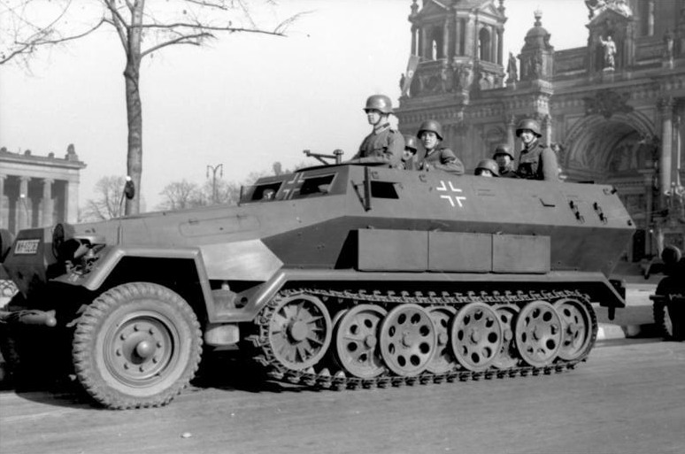
Source: Bundesarchiv via wiki

Post-World War 2, the use of half-tracks diminished. The thought behind the half-track as one combining a simple short track unit with the front end of a truck might have served the needs of wartime economies, but it was, in practice, simply not as effective as a fully tracked vehicle. In the US, for example, the M3 type half-track was rapidly phased out in favor of fully tracked armored personnel carriers which could also be used for a variety of other purposes. This is probably no better illustrated than by the success of the simple M113 platform. The ‘advantage’ of retaining front-wheel steering was found to be far less effective than a simple track-based steering system and, other than second or third-tier militaries, the half-track all but disappeared. With a long history and seemingly confined to the past, it is perhaps surprising therefore that, in 1998, a brand-new modern half-track fully armored vehicle would be proposed by the VXO Group based in Liechtenstein and designed by Klaus Rantala from Finland. A look at this modern take on the half-track and why in 1998, after a gap of more than half a century since half-tracks were last seen as a ‘normal’ military vehicle, provides a useful insight into why old ideas and technology cannot be completely ignored even in the modern era.
Behind the Design
The inventor of this vehicle was listed on the patent application as Klaus Rantala from Uusikaupunki, on the southwest coast of Finland, the home of the automotive firm Valmet. No details were provided for his age or occupation or to connect him to Valmet, but it is clear from the patent that he was at least mechanically and automotively knowledgeable to more than just an amateur degree.
His invention was submitted by the VXO Group International Ltd., based in Vaduz in the west of Liechtenstein, along the River Rhine where it borders Switzerland.
The connection between a Finnish design and a Liechtenstein application may seem odd, but it is less odd than might be surmised. Liechtenstein (like Switzerland next door) does not have its own national patent office. Instead, patents filed in both countries are managed by the Intellectual Property Office (I.G.E.) based in the Swiss capital of Berne. With no national office in Liechtenstein, the only requirement for an application there is an address and it seems that VXO is a convenient filing front without a business presence for Rantala. This filing advantage may have been used to assist in preventing claims or complaints against his filing or simply to help make the application more accessible to a potential customer.
Layout
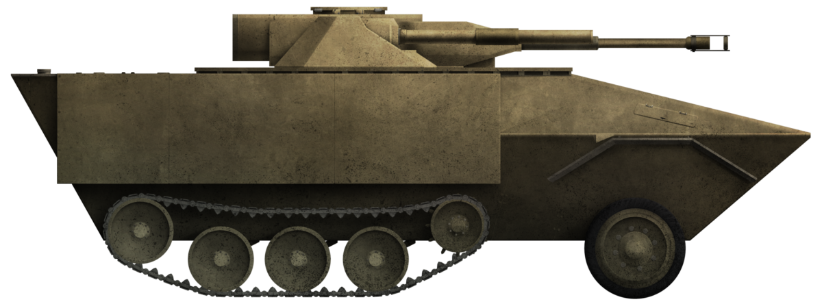
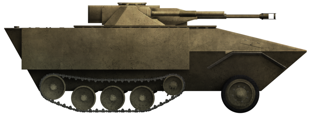
As expected from a ‘half-track’, the rear section of the vehicle in contact with the ground was tracked, with a pair of wheels at the front. The body, rather like the WW2 German Sd.Kfz.251, had sharply angled sides, starting from a narrow lower hull and increasing in width to a position over the tracks and then angling back in somewhat to a flat roofline. The front of the vehicle angled down sharply to the nose over the wheels and was surmounted by an angular turret with two guns clearly visible.

Note that this image has been digitally cleaned.
Source: European Patent EP0103067
The engine for the vehicle was located at the front, directly in line with the front axle, with the driveshaft going backward to the transmission located roughly centrally in the vehicle, in line with the front sprockets. From the transmission, the driving force was delivered to the sprockets on each side and a second drive shaft from this transmission went forwards to the front axles, allowing for driving force to be delivered to the front wheels as well. Thus, the wheels at the front were not just for steering, but would also assist in propelling the vehicle. A final drive element was the driven winch located in the front, which could be used to cross or clear obstacles.

Source: European Patent EP0103067
A pair of circular hatches on the hull roof, in front of the turret, allowed for crew ingress and egress. In case of having to escape without exposing themselves, they could also go through the vehicle and out of the large doors in the rear.

Armor
The shape of the vehicle, with a ‘V’ type hull as far as possible, was intended to improve protection against mines, with a double V at the front by the wheels, where a mine strike might be most likely. The lower hull was at an angle of between 45 to 75 degrees and ideally at 60 degrees to the horizontal. No armor thicknesses were provided or suggested, but the armor was not to be just steel either. Instead, Rantala wanted to use composite materials to improve ballistic protection beyond what could be accomplished with steel alone.
The armor itself was to be a composite formed, as a sandwich with the ‘bread’ being steel outer and inner plates, with a ceramic layer as the jam in between. Where plates were joined, this was to be done by means of tongue and groove joints which were then welded. Rantala offered more than one outline for this concept, but the idea was clear in its goal that layers of steel with another material in between could improve ballistic protection.
That was not the end of the protection either. The heavily sloped sides of the hull sides were to have boxwork fitted to square them off both in the upper and lower halves, adding an element of spaced armor to the design. Across the front third of the vehicle’s length, the whole body was heavily angled but after that, the lower part of the hull was squared off. This would create a much larger storage volume inside the rear portions of the hull.

Unfortunately, without either a weight suggested for the vehicle or an armor thickness, it is not possible to easily estimate the sort of ballistic protection the designer envisaged. At a minimum, protection from small arms fire up to heavy machine-gun fire seems reasonable.
An armored bulkhead separated the engine and transmission components from the crew and cargo/troop space inside, followed by another bulkhead immediately behind the crew space, before the turret. This bulkhead was fitted with large sliding doors to allow the crew to enter or exit the front part of the vehicle from inside the vehicle, as well as having the option of using the roof hatches.
Additional protection for the vehicle and its occupants came in the form of aramid fiber, like Kevlar, which had a high-temperature resistance, clad on the interior.
The fuel tanks were made from manganese steel armor with an explosion-proof inner structure and lay centrally in the vehicle, just aft of the turret. Located low, under the floor in armored boxes, the fuel tanks could be slid in and out on rails.
Crew
A radio operator and a driver occupied the front half of the hull and were separated from the engine by an armored bulkhead. They, in turn, were separated from the space behind by armored sliding doors which operated just behind the line of the circular hull roof hatches.
A single circular hatch was provided on the roof of the turret for the gunner, but he would not sit in there. The turret, in fact, did not project at all into the body of the vehicle. Although the interior of the turret could be accessed and the gunner or anyone else could go in and out via the top hatch, the gunner was safely ensconced inside the body of the vehicle underneath the turret. There was no mention of a separate commander for the vehicle so, presumably, this role would fall to the radio operator in the front of the vehicle or even the driver, at any rate, someone with an easy direct view of the situation to the front of the vehicle. When used as a personnel carrier, up to 8 men would be able to fit in the back, for a total of 11.
Armament
Ammunition for the main gun was to be stored in the rear of the hull for maximum protection from enemy fire. Oddly, Rantala neither described a specific weapon nor even suggested a type of weapon. The drawings, therefore, stand somewhat at odds with the lack of description and the turret clearly features not one but two long-barrelled weapons.
With the turret almost completely undescribed, the only information proffered for it was that it should have a low frontal profile, possess a single roof hatch, and allow the gunner to operate it from below. The images for the turret are therefore the only effective source of evidence from which to draw on Rantala’s ideas.

The two views of the turret provided by Rantala.
Source: European Patent EP937959
The turret can be seen to be small, low, and angular, with what appears to be a well-sloped front flanked by a pair of smaller triangular plates also well angled back, connected to rectangular side plates. The back of the turret is too badly copied on his patent application to be discernible, other than what appears to be a large box-like projection sticking out of the rear. Whether this is a simple stowage box or some kind of ammunition container for an autoloader is not made clear. Having no loader and the gunner in the hull away from the gun does imply the use of an automatic loading system. Also unusual is that both guns in the turret front are offset. The longer of the two and presumably the primary armament on the left has a similar appearance to the French Giat F1 90 mm gun. The one on the right has what appears to be a bore evacuator halfway down the barrel and of roughly a similar size or caliber. Quite why two such guns of a similar size might be required is wholly unclear, but between the two, would suggest at least the capability of firing High Explosive Anti-Tank (HEAT), as well as High Explosive (HE), type ammunition. There is no mention of or an obvious position for a machine gun.
Suspension
Given the similarity to the US and German half-tracks of WW2 already mentioned, it is no surprise that Rantala referenced previous patents for both of those vehicles from 1938 in the case of the American vehicle and 1940 in the case of the German one, as well as more modern patents relating to independent multi-axle suspension and torsion bars, including for a Swedish armored vehicle. This is the normal sort of search report attached to a patent to show it is not simply copying existing work and where the ideas come from.

The front is supported by a pair of tired wheels which would provide the steering for the vehicle, whilst the rear was a tracked unit using three road wheels. A large idler at the back of the unit was raised above the level of the three road wheels and, at the same level, as the idler was the drive sprocket for the tracks, located at their front.

Source: European Patent EP 937634
The three road wheels on each side were connected via swing arms to torsion bars which ran from the end at the swing arm to the center line of the vehicle. Each torsion bar was therefore just half the width of the vehicle and connected to a pivoted moving bar which had a second torsion bar attached to it and running back to the outside of the vehicle on the same side as the first. In effect, this was a half-width version of the double torsion bar system used on the 45-tonne German Panther tank of WW2. This vehicle was clearly not going to be as heavy as that tank, so did not need all of the additional suspension strength, but doubling the torsion bars in this way had two effects. The first was to create an effective torsion bar length of the full vehicle width, allowing for better suspension energy absorption than a single half-width bar, and the second was that it removed the offset wheel problem.
With full-width torsion bars, the pivot point for the swing arms on one side of the vehicle does not line up with the swing arms on the other side, as that point on the opposite side is occupied by the end of the bar. Thus, the wheels are offset and, whilst this may not seem like a big deal on a heavy and relatively slow vehicle like a tank, it is a problem on a smaller and lighter vehicle, where the added impulse of the vehicle trying to slew left or right is stronger. Making the swing arms on one side line up with those on the other completely avoids the problem.
An added detail on the swing arms is that not only is each one fitted with its own damper, but they ran in the opposite direction to travel with the exception of the arm for the idler, which notably ran in the opposite direction. This would mean the movement of the vehicle was ‘into’ the track run rather than vertically into the body of the vehicle.

Note that this image has been digitally cleaned.
Source: European Patent EP937959
Propulsion
The design carefully considered how to add amphibious capacity beyond simple buoyancy and propulsion by the tracks. For this design, two additional systems were added to improve amphibian performance. The first was around the turret. Where the circular turret met the square roof plate, there were corner sections that were formed into air grilles. The two grilles forward of the turret served as air-intakes, which would draw in air inside the vehicle and push it forwards via a channel inside the hull, and then blow that air down via a vent behind the front wheel. These air intakes in front of the turret also served to draw in the air which was needed for ventilation inside and for the operation of the engine. Air and water would then be drawn back into the vehicle and carried underneath the incoming air through a different channel to be expelled via the two vents behind the turret. In theory, this should provide a small air cushion for the front of the vehicle to ride on, although quite how well this might work in reality is unclear. The air-outlet behind the turret was also used as the exhaust outlet for the engine.
This was not the water propulsion system either. That was done by way of a far more conventional impeller-driven system, with the water intake using the same intake grille behind the front wheels on each side. An impeller at the front of this vent, just behind the grille, pulled the water in and sent it down the channel within the lower half of the box work on the side and squirted out of the back of the tube by a second impeller at the rear. This water was to be ejected slightly upwards at an angle of around 20 degrees to help provide a downwards force on the rear of the vehicle.
With the tracks and wheels also being driven at the same time, there are 3 and maybe 4 (if the air/water jet system worked to provide a forward impulse) systems working together to propel the vehicle through the water. Assuming the air cushion and jetting worked, there is no reason the vehicle would not be able to attain a good in-water speed.

Other Uses
As a final aside in his application, Rantala described that, although the vehicle might find best use for military purposes, it could, if need be, be used for civilian uses too. In this, he envisaged that it would make a good forest fire fighting vehicle with the gun replaced with a water cannon with a large water tank in the rear. With the composite armor design able to resist the heat of the fire and filling the tires with water, Rantala thought this would suffice. Oddly, he did not suggest making use of the amphibious capability directly for civilian use.
Conclusion
The design from Rantala was certainly not the work of a casual amateur. The work on the complex air and water channel systems certainly showed a great deal of thought and effort had gone into making the design as viable as possible, both in terms of adding protection but also for incorporating elements of an amphibious drive system.
The turret is somewhat of an enigma. There is seemingly no similar turret carrying guns in the manner of this design, nor a compelling reason offered for being armed in this way.
There is no reason why Rantala’s design was not perfectly viable. The principles behind half-tracks were not revolutionary or untested and had already been in existence. The system clearly worked and all he was doing was adding an amphibious propulsion system to an existing concept. That propulsion system was not revolutionary either, being very similar to a system that was already in widespread use on vehicles like the LVTP-7, so what he was doing really was trying to combine multiple existing technologies into one package and improve on the vehicle as a whole as a result. The real problem with the concept for Rantala seems to be that he chose a half-track which, by the 1990s, was already going to be seen as something very much in the past regardless of what smaller benefits it might have over a fully tracked vehicle.
Likely, the most valuable part of the design was the most understated, even though it was one whole patent in itself – specifically, the torsion bar layout. Torsion bars were most certainly not new in the 1990s, but his idea was both elegant and simple in its effectiveness, using the two half-width torsion bars connected along the center line so that it removed offset wheels as a problem. The problem, however, was obviously just not enough of a problem to catch enough attention or interest in solving it in this way.
The idea of this vehicle combining all of these elements was therefore simply not going to go anywhere and whether VXO or he sought serious offers for licensing or sales is unclear. The idea is, for all intents and purposes, now a dead and defunct one and the design languishes on paper seemingly to never become reality.
This article has been sponsored by CFAH. They are a health and wellness website centered on CBD oils and they have even done an article explaining how these might help with PTSD.
Sources
European Patent EP937959, Amphibious Armoured Vehicle. Filed 21st February 1998, granted 25th August 1999.
European Patent EP0937634, Tracked vehicle with torsion bar suspension. Filed 21st February 1998, granted 25th August 1999.
Weinmann Zimmerli on mondaq.com, 2018 https://www.mondaq.com/patent/673584/switzerland-and-liechtenstein-the-particularities-of-patent-prosecution
VXO/Rantala Amphibious Halftrack specifications |
|
| Crew | 3 (Gunner, radio operator, driver) + up to 8 men carried |
| Armament | 2 large calibre guns with at least one potentially automatically loaded. |
| Armor | Composite (steel/ceramic) |
| For information about abbreviations check the Lexical Index | |
5 replies on “VXO Amphibious Half-track”
Ok now we need a page about Armor of Liechtenstein! I bet it would be limited to some APCs used by local SWAT or something.
Ka;lrin, Liechtenstein does not have a military, its defence is garanteed by Switzerland and Austria. Likewise, its police force is small and does not have a SWAT unit. If anything heavy goes down (and it hasn’t so far!), they’d probably call on support from either Austria or Switzerland.
This looks like a cross between a m3 half-track and an Italian r3 armored car.
WHERE IS THIS IN WAR THUNDER?????
You say this like War Thunder doesn’t require a vehicle to have been built… This would never be added. It was never genuinely considered for production, there’s no specified engine, there’s no specified armament, there’s no physical prototype.. This would be entirely guesswork. There are paper designs, and then there’s this.