 Kingdom of Norway (Mid-1970s-1993)
Armored Recovery Vehicle – 4 Converted
In 1946, Norway began to operate a fleet of M24 Chaffee light tanks given to it under a United States-led Military Aid Program (MAP). By the 1960s, the M24 was still in service with the Norwegian Army (Hæren) and was starting to show its age.
In the late-1960s, the Norwegian Military (Forsvaret, Eng: “The Defence”) began an upgrade program with the company of Thune-Eureka A/S, based in the country’s capital, Oslo. This program was aimed at drastically upgrading the M24 Chaffee fleet with the introduction of a new 90 mm main gun, a new, more powerful engine, a new transmission, and various other modernizations.
While this upgrade program was underway, it was also decided that the upgraded Chaffee – which would receive the designation NM-116 ‘Panserjager’ (tank hunter) – would need a support vehicle. As such, the NM-130 Bergepanser (Armored Recovery Vehicle, ARV) was conceived. Just four vehicles would be converted, but they would all go on to support the NM-116 throughout its service life.

Foundation: The M24 Chaffee
The M24 Chaffee, named after Army General Adna R. Chaffee Jr., entered service in 1944, largely replacing the M3 and M5 Stuarts. It was a small tank at 16 foot 4 inches (5.45 m) long, 9 foot 4 inches (2.84 m) wide, and 5 foot 3 inches (2.61 m) tall. It was also light at just 20.25 tons (18.37 tonnes). Armor on the vehicle was ¾ inch to 1 ½ inch (19 – 38 mm) thick. It was armed with the 75 mm Lightweight Tank Gun M6. It was operated by a 5 man crew, consisting of the commander, gunner, loader, driver and assistant driver/radio operator.
It was a very maneuverable vehicle, powered by a Twin Cadillac 44T24 8-cylinder petrol engine producing 220 hp. The transmission and drive wheels were located at the front of the vehicle. The Chaffee rolled on 5 roadwheels attached to a torsion bar suspension. The fifth road wheel was attached to the idler wheel at the rear of the running gear. This is because the idler was of the compensating type, meaning it was attached to the closest roadwheel by an actuating arm. When the roadwheel reacted to terrain, the idler was pushed out or pulled in accordingly, keeping constant track tension.
Norsk Chaffees
Norway received its first Chaffee’s from the US under the ‘MAP’ in 1946. The ‘Military Aid Program’ benefited the war-ravaged countries of the Second World War by providing them the means to rebuild their military and defenses. Norway was one of these countries that was rebuilding after the lengthy Nazi Occupation of the country. Other countries that benefited from the MAP included France, Portugal, and Belgium, but also former enemy nations such as West Germany and Japan. In April 1949, the North Atlantic Treaty was signed and NATO was born, resulting in the United States prolonging its Military Aid Programs.
The initial 1946 delivery consisted of just 9 vehicles. These were sent directly to Trandum leir, a Norwegian Army Camp (now closed) near Ullensaker. From 1946 until the early 1950s, Norway received a total of 125 M24s. The M24s gave the Norwegian Army (Hæren) excellent service for many years, until the late-1960s. Some went on to serve with the Heimevernet (Home Guard).

The Conversion
The NM-116 was the result of a military on a small budget trying to improve the lethality of its tank arsenal. The NM-130 was the result of the same sort of dilemma; how do you provide a new tank with a new support vehicle without breaking the bank?
Of the Hæren’s 125 M24s, 72 would go on to be used in the NM-116 upgrade program. To develop the ARV, four extra M24s were set aside. As said above, most of the remaining M24s went into service with the Heimevernet. Any remaining vehicles were likely scrapped. It is not uncommon for recovery vehicles to be based on the same chassis as the vehicle they are designed to support. The American M103 heavy tank-based M51 Heavy ARV and German Leopard 1-based Bergepanzer 2 are prime examples of this.
The conversion work to turn the vehicles into ARVs was undertaken by Kvaerner Eureka AS. The four Chaffee hulls went through the same automotive upgrades as those being upgraded to the NM-116 standard. The turrets, however, were completely removed and replaced with a large crane. A small dozer blade was also installed on the vehicle’s lower glacis.

Crew
The NM-130’s crew consisted of three personnel; Commander, Crane Operator and Driver. The driver sat at the front left of the vehicle, as on the original Chaffee. The Commander sat in a position roughly halfway down the length of the hull, on the right side, under a large circular hatch with an incorporated periscope. The Commander was also responsible for the vehicle’s only weapon, a German-made 7.62 mm MG3 machine gun. This was a defensive weapon only. The crane operator sat in an external, unarmored position on the crane unit when it was in operation. When it was not in operation, it is unknown where he would have sat. It is likely that he sat in what would have been the bow gunner’s position on the standard Chaffee, at the front right of the hull. Concrete evidence of this escapes the author at the time of writing.
Dag Rune Nilsen, ex-commander of an NM-116 from Panserverneskadron, Brigade Nord (PvEsk/N, Eng: “Tank Squadron, Northern Brigade”), describes here the working relationship with the NM-130 and its crew:
“The NM-130 crew was an important part of the Panserverneskadron. It was manned by the mechanics who maintained our vehicles at base, so we had a close working relationship. I got the impression that they were very happy with the vehicle and [they were] proud to operate it. It had a strong winch, a solid crane and other tools including a welding machine. Our squadron operated M113s, NM-142s and, of course, the NM-116. The NM-130 were capable of assisting us in all the situations we encountered. No problems whatsoever.”

Automotive Upgrades
The Chaffee’s Twin Cadillac 220hp petrol engine was replaced by a Detroit Diesel 6V-53T two-stroke diesel engine that was liquid-cooled and equipped with a turbocharger. Diesel engines perform better in cold temperatures and are also somewhat safer as diesel is less volatile than petrol (gasoline). The engine gave the tank more power as it produced 260 hp, but slowed the tank down to a top speed of 47 km/h (29 mph). This was not too big of an issue as the increased torque gave it the power to navigate Norway’s tough terrain. Two, 208-liter (55 gallons) fuel tanks also gave it a greater range of 300 kilometers (186 miles) compared to the 160 kilometers (100 miles) of the original powerplant. Four heat exchangers were also installed to cool the engine’s oil.

The original ‘Hydramatic’ transmission was also replaced with an Allison MT 650/653 pre-selector 6-speed (5 forward, 1 reverse) gearbox. An additional gearbox was installed to control the speed transferred to the differential housed at the front of the tank.
In this crane adaption, two hydraulic pumps were installed in the engine compartment to power the hydraulically operated crane, winch, and dozer blade.
Crane
The crane (No: kran) chosen for the Bergepanser was the BK710MIL made by Moelven-Brug A/S – now known as CHSnor. For the installation of the crane, a solid metal plate was welded over the turret ring. The base of the crane was then fixed to the top of this. The crane is capable of full 360-degree rotation. When not in operation, the crane is rested at 0 degrees, with the boom fully retracted. The whole unit is then swung 180 degrees so it points over the vehicle’s engine bay.
The crane consists of a large boom with an integral, external control position. The crane’s boom is of the telescopic type, being able to extend from 3.4 meters (11.1 ft) to 5 meters (16.4 ft). The boom can travel on its vertical axis from 0 to +55 degrees. It is raised and lowered via a hydraulic ram underneath the boom, at its base.

A hydraulically driven winch was mounted at the base of the crane boom. The winch cable runs externally up the spine of the boom to a large single guide wheel at the tip of the boom. The cable ends in a simple clevis rather than a hook. A large cable-guard safety grate was also mounted at the base of the crane to protect the operator.

The crane had a maximum lift capacity of 7 tonnes (7.7 tons), as long as the boom was not raised over 25 degrees upwards. If the crane was raised to 25 degrees of elevation or over, the maximum load was reduced to 2 tonnes (2.2 tons). The crane had a relatively low lift capacity as it was not designed to lift the entire vehicle, but just its components. The 2-7 tonnes lift capacity was more than enough to hoist the NM-116’s Detroit Diesel engine which weighed just 600 kgs (1323 lbs).
While Dag Rune Nilsen never required the use of the Bergepanser personally, he was witness to it assisting his comrades as he describes in the following story about a powerpack lift:
“The NM-130 did assist my good friend Sergeant Storli when he had to change the engine on his tank, callsign 12, name of ‘Aratos’, in the field. I remember the mechanics requesting if they could tow the broken NM-116 to the nearest military garage. The request was denied and they had to change the engine in freezing cold weather in the open during the night! Good realistic practice even though the crew disagreed!”

The steel-wire cable utilized by the crane was 22 mm (0.8 in) in diameter and had a capacity of 19 tonnes (21 tons). Despite the crane having a meager capacity of 2-7 tonnes, it was necessary that the cable be stronger so it could tow or retrieve the NM-116. For this, the cable was threaded through fairleads (a device that guides a line, rope or cable) placed behind the drum. This allowed the vehicle to tow vehicles behind it. To do this though, the crane would have to be traversed 180 degrees. Judging from the few available photos of the NM-130 in service, it would appear that crane’s boom was used as a stowage point for the crew’s personal packs and effects, as well as camouflage nets and other sundries.

Crane Operator’s Position
The Crane Operator’s position was incorporated into the crane boom and was mounted on its right. The position consisted of a padded seat and a control desk. It was completely open to the elements and was without armor protection. Operation of the boom was rather simple, with basic levers that raise, lower, swing, extend/retract the boom, and let-out/reel-in the winch cable.

Dozer Blade
Much like the dozer blade (No:bulldozerblad) found on the American M88 ARV, the NM-130’s dozer blade performed three main roles: light earthmoving operations/obstacle clearance, support during lifting operations, and anchorage when winching.
The hydraulically operated blade was shallow but roughly vehicle width at 2.84 meters (9 ft 4 in) and was mounted on the bow. It moved up and down via two large hydraulic rams mounted above it. The blade was operated by the driver. To avoid breakages while earthmoving, the front-wheel stations of the vehicle were reinforced. During the lift and winching operations, the blade acted much like outriggers on a conventional crane and lifted the front end of the vehicle off the ground to stop it shifting on its tracks.

Other Features
As with the NM-116, the Bersepanser received the same 73-link split rubber block tracks made by the German company Diehl. At some point, the NM-130 also received the same sprocket upgrade as the NM-116. The new sprocket wheel had smaller and fewer teeth. The original Chaffee sprocket had 13 teeth while the newer one had 12. This was likely done to improve the compatibility with new track types. Also, while the NM-116 kept just two of the original four shock absorbers, the NM-130 kept three, with two at the front, and one at the rear.

The same eight smoke-grenade launchers, or Røyklegginganlegg (Smoke Laying Device), that were added to the turret of the NM-116 were also installed on the NM-130. They were mounted on the left and right fenders in single banks of four. These German-made devices were electrically fired, and were used to launch the 76 mm (3 in) Røykboks (smoke grenade) DM2 HC grenade. In total, 16 smoke grenades were carried and, if necessary, all loaded grenades could be fired at once.

Other features included the introduction of large tool/stowage boxes on the rear of the left and right fenders. On the back right corner of the engine deck, there was a stowage point for extra pulleys and clevises for winching and hoisting. There was also a point on the right rear of the hull for carrying a spare NM-116/130 roadwheel. Steel-wire tow cables were carried on the right fender, with tools such as an axe and sledgehammer carried on the hull wall above them.
It was not uncommon for crews to carry their own selection of preferred equipment, as Dag Nilsen describes:
“NM-130 mechanics improvised and added additional equipment that experience had shown they needed. The crew that assisted Sergeant Stoli, for instance, carried a welder. In my own experience of NM-116 crews, we would regularly amend the tanks for comfort and for practical purposes. I believe NM-130 crews did the same.”

Service
Unfortunately, much like the NM-116, details of the Bergepanser’s time in service are scarce. The vehicles entered service in the mid-1970s; an exact year is unknown but it was probably around the same time as the NM-116, in 1975. How the four ARVs were split between the 72-strong NM-116 fleet is also unknown. However, it is known that he only full-time operator of the NM-116 was the Panserverneskadron, Brigade Nord (PvEsk/N, Eng: “Tank Squadron, Northern Brigade”). At least two NM-130s were part of this Brigade. The vehicle was also capable of supporting Norway’s fleet of US-made M113 Armored Personnel Carriers (APC) and derivative there of, such as the NM-142 (TOW) Rakettpanserjager.
This quote from Dag Rune Nilsen provides a small insight into the NM-130’s use:
“I never required assistance myself (pure luck!) but I did indeed witness the recovery team rescue many of my comrades. The terrain we operated in was brutal all year around and absolutely not ideal for tanks. It was quite common to lose the tracks or to sink into deep snow. Most of the time we managed to do self-recovery through various tricks but the NM-130 could always be counted on. It would cost the commander a case of beer though! The winch was the multipurpose tool for recovery and could drag an NM116 easily onto safe ground.”

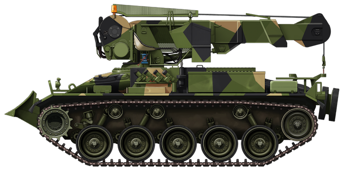
Like the NM-116, the vehicle initially entered service in an olive drab livery but, in the mid-1980s, a new ‘Splinter’ camouflage pattern was introduced. The NM-130 would see out its service in this livery.
The NM-116 was retired in 1993. It is unclear when exactly the NM-130 was retired, but there is a possibility that it stayed on in service a little longer to serve Norway’s fleet of M48s and Leopard 1s, but concrete evidence of this cannot be found.

Conclusion
In the NM-130, the Forsvaret achieved its goal of providing an effective recovery vehicle to not only the NM-116, but the Hæren’s other light vehicles too, all while sticking to a strict budget. Just like the NM-116, the NM-130 was an ingenious use of what was – at the time of its development – an almost thirty-year-old piece of Second World War hardware.
Dag Rune Nilsen perhaps describes it best:
“I would describe the NM-130 as a fit for purpose recovery tank, and thus a very successful modification. Much more successful than the NM-116 itself since the NM-130 did exactly what it was intended for and remained effective for its entire service life.”
It is unclear how many of the four NM-130s survive. The one featured in most of the photos used in this article was located – until recently – at the Rena Army Camp, eastern Norway. Where it is now is unknown. At least one NM-130 can still be found at the Rogaland Krigshistorisk Museum, also in Norway.

An article by Mark Nash, assisted by Steffen Hjønnevåg.
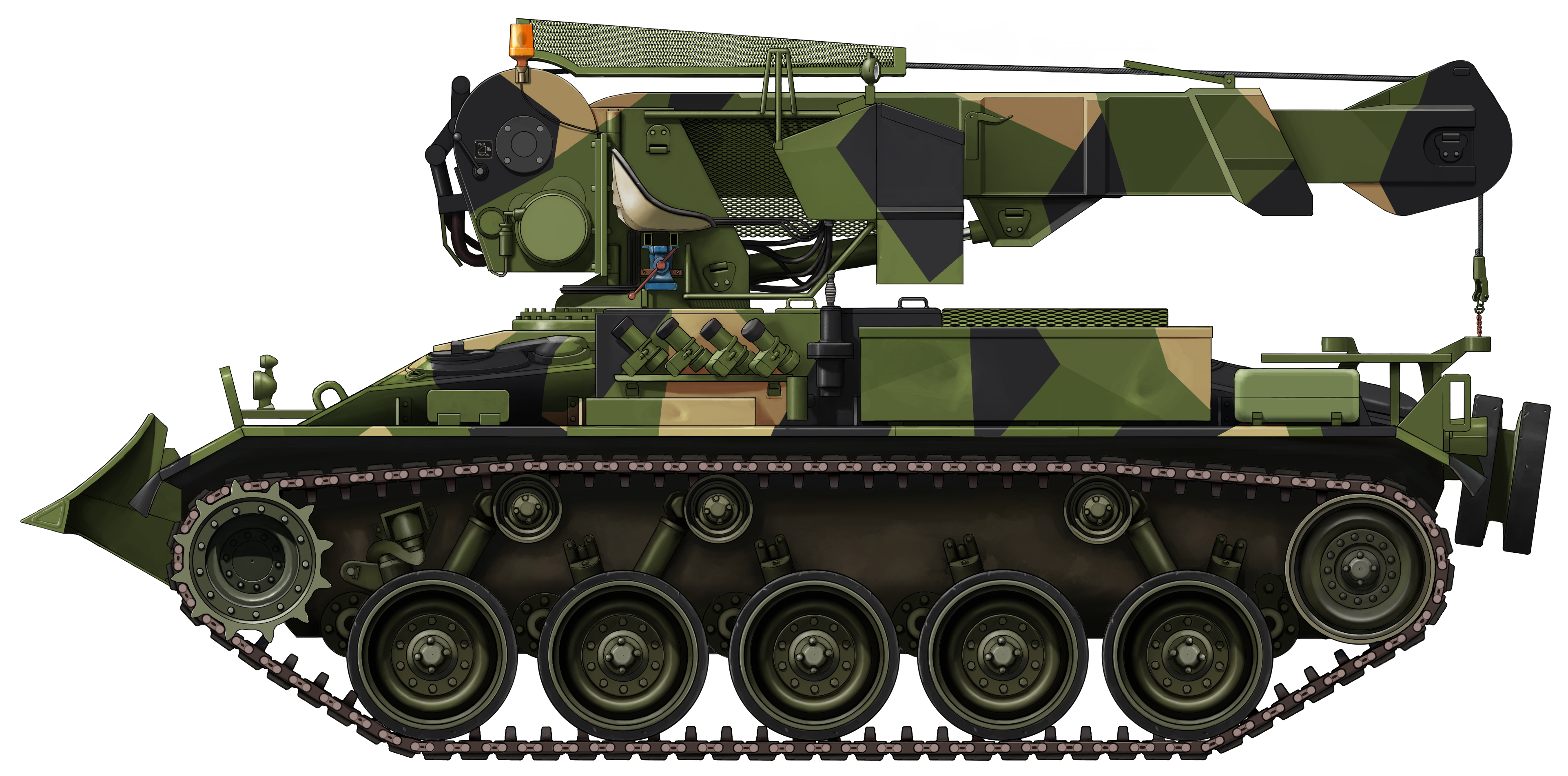
An NM-130 Bergepanser in ‘Splinter’ camouflage with the Crane in its travel position. Illustration produced by Ardhya Anargha, funded by our Patreon campaign.
Specifications |
|
| Dimensions (L-W-H) | 5.45 x 2.84 x 2.61 meters (16’4″ x 9’4″ x 5’3″) |
| Total weight, battle ready | Aprx. 18.3 tonnes (20 tons) |
| Crew | 3 (commander, crane operator, driver) |
| Propulsion | Detroit Diesel 6V-53T, 260hp |
| Max Road Speed | 47 km/h (29 mph) |
| Range | 300 kilometers (186 miles) |
| Armament | 1x 7.62 mm MG3 machine gun |
| Equipment | 2 – 7 tonne (2.2 – 7.7 ton) capacity crane 19 tonne (21 ton) winch 2.84 meters (9 ft 4 in) wide Dozer Blade |
| Front Armor | 25 mm (1 in) |
| Front Side 2/3 Armor | 25 mm (1 in) |
| Rear side 1/3 Armor | 19 mm (3/4 in) |
| Rear Armor | 19 mm (3/4 in) |
| Production | 4 |
Sources
2nd Lieutenant Dag Rune Nilsen, Former NM-116 Commander, retired
Teknisk Håndbok, Panserjager NM-116: Beskrivelse, Behandling, og Brukerens Vedlikehold (Eng: Technical Manual, Panserjager NM-116: Description, Treatment, and User Maintenance). Available at modellnorge.no (Flash player required).
Clemens Niesner, Norge – Hærens Styrker, Vehicles of the Modern Norwegian Land Forces, Tankograd Publishing
hestvik.no
modellnorge.no
www.primeportal.net
11 replies on “NM-130 Bergepanser”
Great article covering a little known vehicle. Detailed and thorough. well done!
Thanks, Dag!
– Author
Can you please contact me on:
[email protected]
Best regards,
Henk
Thank you Dag for serving your country and thank you for being a wonderful source of information for these Norwegian tank articles.
Thank you so much Aaron! It is nothing but a pleasure to share this information and photos:-) It doesn’t take long before both information and not least photos disappear (own experience). I am happy that there is such an excellent resource as the Tank Encyclopedia!
Hello Dag,
Can I get in contact with you? I am looking for more info on a particular serial number of a NM-130.. Thank you.
Best regards,
Henk
Totally agree. Nice picture Dag Rune:-)
Are you guys thinking about doing an article for the NM142 tank destroyer? I remember Mr. Nilsen mentioning he’s driven in one of those. Not to mention it’d be a worthwhile vehicle to cover.
It will definitely be covered at some point. Even with Dag’s help, information on the vehicle is scarce, however.
– Author
Thank you for a great article on one of my favorite vehicles.
I served on NM116s in the late 70s. In 1979 my crew and I was converted and trained on recover operations as the first qualified crew on the NM130 in order to take part in user trials on the prototype vehicle. Later in 1979, we participated in acceptance test of the next three production vehicles. During my years in the cavalry, I continued to serve for some time on this vehicle.
So the NM130 entered service in 1979 and was phased out in about 1994 together with the NM116 as a result of the CFE treaty.
Total number of vehicles converted was 8 (including the prototype). We had 8 squadrons each consisting of 9 NM116 (3 platoons of 3) and 1 NM130 (peacetime organization varied dictated by practicalities). Hence 72 and 8 in total.
During lifting or recovery operations, the crane operator sat on the crane, the driver was in his position or on the ground and the commander was on the ground directing the activity. For this he had a handset with 50 m of cable, connected to the intercom. While driving, the driver had his position front left. The position to the rear, right of the crane was intended to be the commanders position and the front right position was intended to be the crane operators position. I found this to be impractical since the field of view from the rear position was to limited. I always sat at the front right position where I could better navigate and direct the driver. The crane operator sat at the rear and had to assist when reversing.
The NM130 was armed with two 7,62mm MG3s. One on a DISA flexible mount that could be mounted either on the crane next to the crane operator or next to the rear hatch. I always kept this weapon mounted on the crane for use against air targets. The second MG3 was mounted on a fixture connected through the regular M24 front MG mount. This fixture elevated the MG3 above the dozer blade when this was in traveling position and enabled the weapons to be fired from inside with the hatch closed. The ammunition box was mounted on the front behind the dozer blade so the weapon could only be reloaded from outside.
As stated, the lifting capacity of the crane was limited (2 to 7 tonnes) but it was sufficient for lifting the NM116 engine and turret. It was also sufficient for lifting the power pack of the Leopard 1 weighing 4,8 tonnes. The vehicle’s main strength was the pulling capacity of the winch having 70 meters of wire and managing up to 19 tonnes on a single wire pull. A pulling force of 57 tonnes using triple wire pull have been measured. The vehicle was also well equipped with regular tools, power tools, welding and cutting equipment end a chain saw. Larger spare parts however had to be transported by other means.
Hope this can help covering some of the blank areas in the original article.
Thanks for the insight, Terje! We’ll work on getting it added. Please contact us if you have any further information!