 Soviet Union (1942)
Amphibious Light Tank/Armored Personnel Carrier – None Built
The idea of amphibious armored vehicles appeared concurrently with the creation of the first tanks. With the first prototypes appearing at the end of WWI (the British Medium Mark D, for example), such vehicles gained popularity amongst armies of all major nations of the Interwar period, including the USSR. One of the main disadvantages of such vehicles was a low speed in water, which rarely surpassed 10 km/h. In 1942, Soviet inventor Nikolay Vetchinkin came out with a unique vehicle concept that could have become the fastest amphibious tracked vehicle ever.
Soviet Light Amphibious Tanks by 1942

The history of Soviet light amphibious tanks goes back to the early 1930s. In 1931, Soviet military command received information about successful trials of the A4E11/A4E12 Vickers-Carden-Lloyd light amphibious tank. In response, the Soviet military leadership launched a program to develop a domestic counterpart. The resulting vehicle was the T-33 light amphibious tank, also known under the nickname ‘Selezen’ (rus. ‘селезень’, stands for ‘drake’ – the male duck). However, it was too crude and had plenty of serious drawbacks that left no chance of mass production.

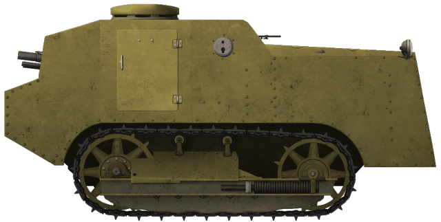
The T-37 amphibious reconnaissance tank was developed under the leadership of S.A. Ginzburg and put to the test in July 1932. Its layout was similar to the T-33 and the Vickers-Carden-Lloyd light amphibious tank. The T-37 had a riveted-welded hull made of non-armored steel. A manually rotated turret was installed on the hull’s roof, shifted to the left side. The armament of the tank consisted of a 7.62 mm DT machine gun mounted in a ball mount in the front plate of the turret. The T-37 prototype became the basis for the creation of the T-37A tank, which was adopted by the Red Army in 1933.

The T-41 tank underwent trials in early July 1932. It had a riveted-welded hull and a combat weight of 3.5 tonnes with a crew of two consisting of a driver and a commander. Positioned on the hull’s roof, a manually-rotated turret, which was shifted to the right side, was installed on a ball ring. The vehicle was equipped with a 7.62 mm DT machine gun for armament, which could only provide firing angles of 33º horizontally and 24º vertically without rotating the turret. A 40 hp Ford-AA automobile engine, enabling the tank to achieve speeds of up to 35 km/h on the road, was installed longitudinally along the central axis of the vehicle. The 120-liter fuel tank was located at the rear left side of the hull, with fuel supply being gravity-fed. The tank had a range of 150 km on the road. In water, the T-41 employed a two-bladed propeller and a flat rudder for movement, capable of traveling both forwards and backwards. It could reach speeds of 3-3.5 km/h while afloat.

Taking into account the experience gained in the design of the T-41 and T-37 vehicles, a new amphibious tank was put into development for its adoption by the Red Army. It was assumed that the vehicle would be similar in layout to the T-41, but with a suspension from the T-37. On August 11th, 1932, even before the production of the prototype, a new tank, designated T-37A, was adopted by the Red Army.
The tank had a hermetic hull made of rolled armor plates. The transmission was located in the front of the hull, the driver/mechanic was located on the left and the commander on the right. The engine, a 40 hp GAZ-AA, was located at the rear. To increase buoyancy, pontoons filled with cork were attached to the sides.
The T-37A was used in large numbers during the Soviet invasion of Poland and in the Winter War against Finland.

The operation of T-37A amphibious tanks revealed several disadvantages, including an unreliable transmission and chassis, tracks that frequently detach, and inadequate range both on land and on water. Therefore, in late 1934, the Design Bureau of Plant No. 37 was tasked with developing a new amphibious tank based on the T-37A. The T-38 tank prototype underwent trials in June 1935. During development, the engineers made every effort to incorporate elements from the T-37A, which had already been well-established in production. The T-38 had a similar layout to the T-37A, with the driver positioned on the right and the turret on the left. In comparison to its predecessor, the new tank featured a wider hull without additional pontoons on the sides. The turret and armament remained largely the same, with only minor improvements, as did the engine. On February 29th, 1936, the T-38 tank was officially adopted by the Red Army, replacing the T-37A. Mass production of the new amphibious tank began in the same year, running in parallel with the production of the T-37A for a period of time.

In April 1938, the Armored Vehicle Directorate of the Red Army issued tactical and technical requirements for the development of a new amphibious reconnaissance tank. As per the task, the Design Bureau of Plant No. 37 was assigned to design a vehicle weighing up to 4.8 tonnes, with a two-person crew, armor thickness of up to 13 mm, and armed with 12.7 and 7.62 mm machine guns. Owing to the lack of a diesel engine with suitable power, it was intended to use an imported Dodge automobile engine. Serial production of this engine, under the GAZ-11 label, was to be established by the Gorky Automobile Plant (GAZ). The new tank was designated T-40. The development of the tank ended at the end of 1938, and the blueprints were immediately transferred to production. By spring 1939, the first samples of the vehicle were completed.

The new tank had notable distinctions compared to its predecessors. It featured an elevated body height, constructed with welded armor plates ranging from 6 to 13 mm thickness. To enhance buoyancy, it adopted a trapezoidal shape with an expanded upper part. The crew of the tank consisted of a driver and a commander. Moreover, the tank’s armament was upgraded: the turret, resembling a truncated cone, mounted a 12.7 mm DSHK machine gun and a coaxial 7.62 mm DT. In the rear part of the hull, there were two fuel tanks with a capacity of 100 l each, enabling an increase in the power reserve to 220 km on the road. The specialized niche in the rear armor plate of the hull housed the three-bladed propeller and flat water-propelled rudders, providing protection against external damage. The suspension for the T-40 tank differed from earlier designs, as it used a torsion bar instead of a sprung bogie system. Each side of the vehicle featured four roadwheels, three return rollers, a sprocket, and an idler. The combat weight of the tank was 5.2 tonnes. Since 1941, the T-40 amphibious tanks have been replaced in production by the T-60 light tanks, which had a simpler layout.
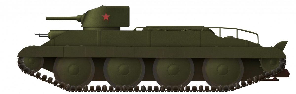
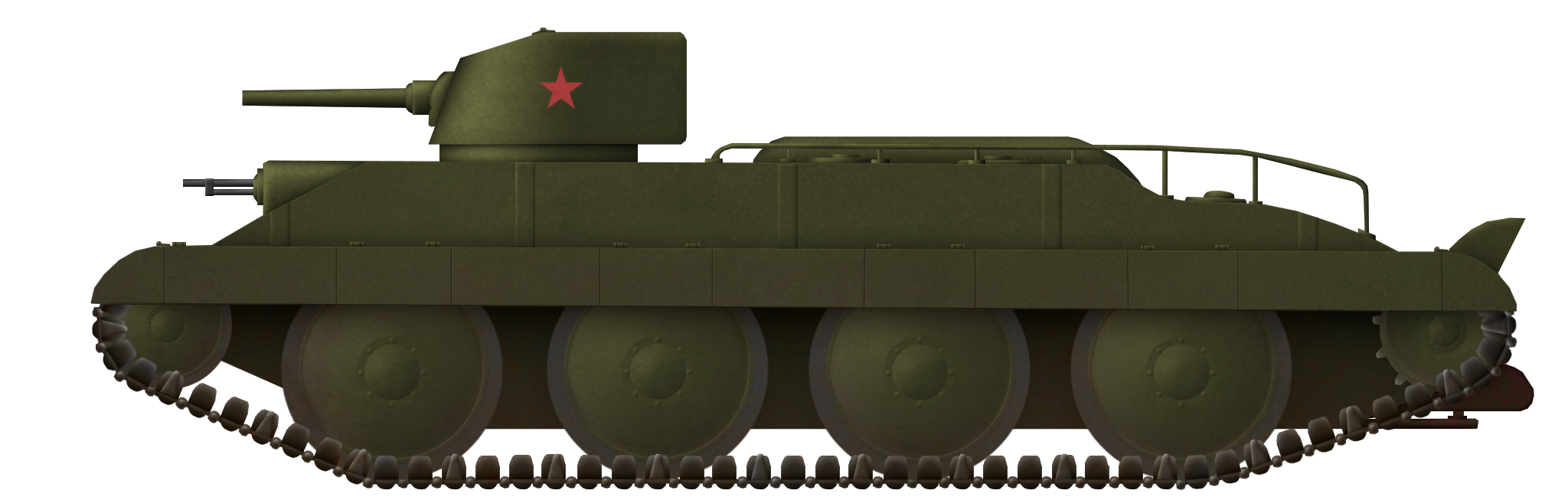
The aforementioned vehicles, descendants of A4E11/A4E12 Vickers-Carden-Lloyd, were not the sole Soviet approach to the concept of amphibious tanks. In fact, categorizing most of them as tanks is difficult due to their symbolic armor, weak armament, limited buoyancy (‘just enough to prevent sinking’), and various other issues. However, during the early Interwar period, the USSR also developed what could possibly be the world’s first amphibious tank with convertible drive and cannon armament – the PT-1. It was also the only vehicle of its kind to reach the stage of combat readiness.

Work on the PT-1 began when the Red Army’s Department of Mechanization and Motorization developed a tactical and technical specification for a medium amphibious tank with a combat weight of up to 20 tonnes. It was to be armed with a 45 mm gun and three machine guns, and crewed by six people. The tank needed to have a maximum speed of 30 km/h on the road and be armored to withstand 37 mm shells at a distance of over 1 km. In August 1930, the specification was sent to the Izhora and Bolshevik plants for further consideration. Based on this, the Technical Department of the Economic Management under the Joint State Political Department developed a project for the amphibious tank PT-1 with a convertible drive.

The prototype of the PT-1 was manufactured in Moscow at the Krasny Proletary factory in 1932 and was tested at the NIBT proving ground. It proved to be so successful that there were plans to start mass production in 1934, with the intention of completely replacing the BT tanks from 1936 onwards. However, due to its significantly more complex layout compared to the fast BT tanks, the PT-1 never made it into mass production.
To sum up, by 1942 the Red Army did not have any up-to-date light amphibious tank. All vehicles in service were tremendously ancient and based on technologies from late 1920s/early 1930s.
Professor Nikolay Vetchinkin (1886 – 1960)
Nikolay Sergeevich Vetchinkin was born in 1886 in the Russian Empire. At the age of 20, he entered the Faculty of Civil Engineering of the St. Petersburg Polytechnic Institute and, being a low-income student, combined his studies with service as a land surveyor of the St. Petersburg Provincial Drawing Office until 1914. In the same year, N. S. Vetchinkin, while remaining a student, became the head of experimental works on mechanized road construction using American machines at the St. Petersburg Provincial Land Management Commission. He received this assignment because he had good technical training and knew English, thanks to which he successfully mastered the designs of American machines, including tractors.

During the First World War, N.S. Vetchinkin worked at fortifications near Petrograd until autumn 1915, and then, at the request of the Main Military Engineering Directorate, he was detached to the Southwestern Front at the disposal of the Kiev District of Railways as an instructor in road construction, where he was later appointed head of machine-road parties. At that time, a base for the repair and construction of road vehicles was organized under his leadership in the city of Fastov, Kiev province. After the war, N.S. Vetchinkin worked in the road organizations of Kiev and Moscow as a senior engineer and head of the experimental work department.
At the beginning of 1920, he was detached to the Moscow Higher Technical School (now The Bauman Moscow State Technical University) at the Faculty of Civil Engineering, which he graduated at the end of the same year. Later, he worked in various important positions in the State Planning Committee of the Supreme Economic Council. In 1921, he became a member of the CPSU and began teaching at the Moscow Forestry Institute, and later, after its merger with the Leningrad Forestry Institute, in the latter. In 1929, he was elected to the post of head of the Department of the Moscow Mechanical Lomonosov Institute and, in the same year, was approved by the State Scientific Council of the People’s Commissariat of Education in the position and title of professor.
From 1927 to 1955, Prof. N. S. Vetchinkin worked at the Research Institute of Economics of the North of the Glavsevmorput (rus. acronym for The Chief Directorate of the Northern Sea Route) on issues of all-terrain vehicles, Arctic amphibians, and cargo transportation over snow. At TsNIIME (rus. acronym for Central Research and Design Institute of Mechanization and Power Engineering of the Forest Industry), he worked on the improvement of gas generators, the use of amphibious all-terrain winches for the purposes of mechanization of alloy, and also conducted pedagogical work in the Belarusian and Moscow Forestry Institutes and Moscow Institute of Advanced Training of Forest Industry Engineers.
N. S. Vetchinkin’s bibliography comprises 84 printed works, including 24 books and brochures. For more than 40 years, he was engaged in inventions and technical improvements and received a number of patents. He died on August 7, 1960, at the age of 74.
Design

Source: TsAMO RF, Fund 38, inventory 11350, case №317.
While designing G.K.A. 1500, Prof. Vetchinkin focused on the driving and floating characteristics of the proposed vehicle, ‘leaving out’ the armament and only vaguely describing the armor protection. Probably, as a true professional, he did not want to mess up the part of design he could not make heads or tails of, and preferred to focus on ones he understood.
Name of the vehicle
Prof. Vetchinkin named his proposal ‘G.K.A. 1500’ (‘Г.К.А. 1500’ in Russian). This acronym stands for ‘Гусеничный Катер-Амфибия’, or Tracked Amphibious Boat. 1500 was the total power of the vehicle’s engines.
Hull
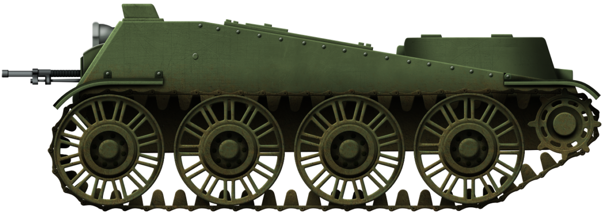
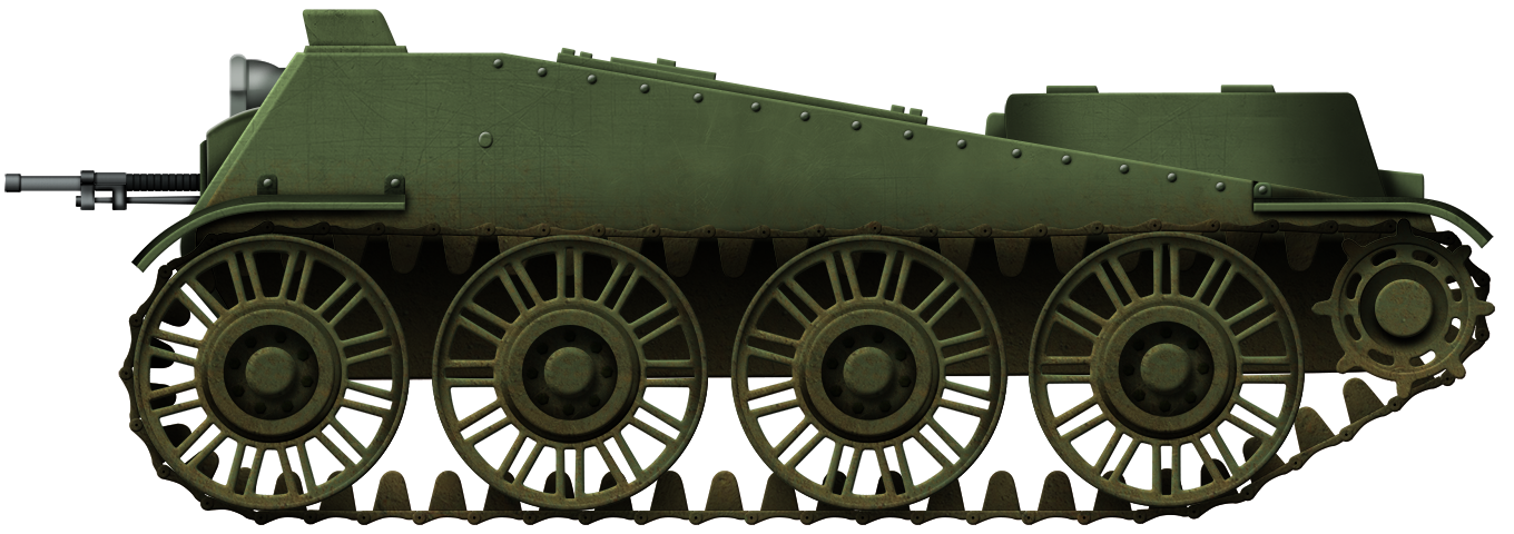
Though, at first glance, the vehicle’s hull resembled those of BT-series fast tanks, it had several major differences. The most striking one was the construction of G.K.A. 1500’s belly. Prof. Vetchinkin was inspired by the ‘Sea Sled’ vessel, invented by Canadian designer Albert Hickman (December 22, 1878 – September 10, 1957), and took the idea of a W-shaped hull. According to the inventor, it would ensure smoothness and softness of the G.K.A. 1500’s course on water.

Source: Phil Bolger’s column in WoodenBoat magazine
According to Vetchinkin, due to the parallel sides and W-shaped belly, the G.K.A. 1500 would have had good stability on water and high seaworthiness.
G.K.A. 1500 had a sloped hull front with a machine gun port on the right side. The proposed vehicle’s length was 9.6 m, which was almost twice as long as that of the BT-7 fast tank (5.66 m) and more than 1.5 times as long as that of the KV-1 heavy tank (6.675 m).
Running Gear
The tracked portion featured four large hollow roadwheels (⌀1.5 m), likely sprung by coil springs (Christie suspension) within the hull, though this is not confirmed by any drawings. They acted as pontoons and reduced the draught when the tank was on the water. The sprocket was at the rear and the idler was at the front. It was not supposed to use any return rollers, as the track return was supported by the roadwheels, which touched the load-bearing track below and the return track above. The propeller and rudder were located below the rear of the hull. Some of the track segments were equipped with extra paddles. Otherwise, G.K.A. 1500’s tracks acted as paddle wheels of an exceptionally large radius.

Source: TsAMO RF, Fund 38, inventory 11350, case №317, modified by Enrico Micheli
All this, according to Prof. Vetchinkin, also improved the seaworthiness of G.K.A. 1500. Hollow pontoon wheels and tracks with paddles would push water onto the propeller, eventually providing the vehicle with high speed on the water.
Propulsion
Nothing is known about the vehicle’s powertrain apart from total power – 1500 hp, which would give the specific power at the extreme level of 88 hp/t. This would have enabled the vehicle’s maximum speed of 50 km/h afloat and 150 km/h ashore. The fuel reserve was provided for 4 hours at full speed and 8 hours at normal.
Armor and Armament
Prof. Vetchinkin never worked out the vehicle’s armament or protection, probably believing that military specialists should be engaged in this. The only thing emphasized was that, in order to increase the buoyancy of the G.K.A. 1500, it would be essential to sacrifice the thickness of its armor.
Crew
G.K.A. 1500 could carry up to 20 men. The cut-out scheme of the engine compartment shows 8 seats per side, so probably 16 infantry dismounts were supposed to be onboard. The remaining four would have probably been the crew: commander, driver, loader, and gunner.

Source: TsAMO RF, Fund 38, inventory 11350, case №317.
Fate and Prospects of the Project
The W-shaped hull had no future because of numerous disadvantages, like the intrusion of the high keel line into the inner compartment, complex construction, deep hull draught due to the displacement volume lost in the tunnel, slow turning due to the flat sides, a tendency to blow water on top, where it then would have washed over the length of the vehicle, compromising air intakes, exhaust and also seaworthiness.
The project would have had many problems, such as thin armor, low reliability and high complexity of maintenance.
The G.K.A. 1500, if built, could have performed various tasks, including coast guard and amphibious operations. Vetchinkin wrote:
“The possibility of a military vessel’s direct exit from the water to the shore, free movement on land and re-entry into the water, combined with a high speed and the ability to fire on the move, like a land tank, can give serious advantages to the navy in a collision with an enemy that does not have such combat means.”
Conclusion
Vetchinkin’s tracked amphibious boat, G.K.A. 1500, was an innovative proposal for its time. It could hardly be rivaled by any other amphibious vehicle of the Second World War period (and, probably, of later ones as well) in terms of speed and seaworthiness. The project obviously required refinements (especially in terms of armament and armor protection) and trials. The Red Army could not afford all that for a single-purpose specialized vehicle in the midst of the war. The Soviet military command did not show any interest in this proposal and it never left the drawing board.
G.K.A. 1500 Specifications Table |
|
|---|---|
| Dimensions (L-W-H) | Length: 9.6 m Width (without tracks): ~ 2 м Width (with tracks): 3.2 m Height: 3 m |
| Total weight, battle ready | ~17 tonnes |
| Crew | 20 men (probably Commander, Loader, Gunner and Driver + 16 troopers) |
| Propulsion | 1500 hp engine |
| Max speed | 150 km/h (93 mph) – ashore 50 km/h (31 mph) – afloat |
| Range (road) | 4 hours at maximum speed, 8 hours at normal |
| Armament | Unspecified gun in turret and machine gun in hull |
| Armor | Unspecified |
| № built | 0 |
Sources
‘Lesnoj zhurnal’, №1/1961, p. 173-174;
TsAMO RF, Fund 38, inventory 11350, case №317;
Maxim Kolomiets. Stalin’s “miracle weapon”. Floating tanks of the Great Patriotic War T-37, T-38, T-40
Yuri Bahurin, “Bronefantazii 40-h godov. Gusenichnye zemnovodnye”;
Phil Bolger’s column in WoodenBoat magazine;
https://www.bronetehnika.narod.ru/t40/t40_2.html;
https://bronetehnika.narod.ru/pt1/pt1.html;
https://shushpanzer-ru.livejournal.com/392240.html;
https://modelist-konstruktor.com/avtosalon/plavayushhie-traktory;


