Categories
Pre-WW1 British Armor

Wolseley / Hamilton Motor Sleigh

United Kingdom (1910-1916)
Antarctic Transportation Vehicle – 3 Built

The interior of the continent of Antarctica was virtually unknown even into the start of the 20th century and the quest for being the first to reach the South Pole was one of the great exploration challenges at the start of the century. When it came to exploring this dry and frigid environment, transport across ice, which could range from as hard as rock to soft snow in which a man could sink to his waist, was as difficult and arduous as it was hazardous. In preparation for the Scott ‘Terra Nova’ expedition of 1910 – 1912, the latest in technological advances was taken with the team – the motorised sledge. Running on tracks, these sledges were to carry the tonnes of supplies the men needed during the months they would spend on the ice. The sledges proved to be a failure and, given that the men involved were mostly drawn from the Royal Navy, this helped to color the perception of tracked vehicles immediately prior to WW1. Mentioned as an example of an early tracked vehicle and particularly in the context of the disaster of the Scott mission, the motor sledge became, as a tracked vehicle, synonymous with failure.

The sledge, however, was both innovative and one of the first tracked vehicles ever used by members of the British military. It had no armor and no weapons ever fitted but it fills an important position in the development of British military tracked vehicles. As such, a close look at the sledge provides insights into why it was a failure and lessons and perceptions of tracked vehicles which colored the views of men like Admiral Sueter (a man not shy in promoting himself as the originator of tanks) right at the dawn of the invention in 1915. Sueter, in fact, credits himself with suggesting tracks to Scott, whom he knew as a fellow naval man.

Landing at McMurdo Sound and setting up camp, it was a long cold route across the ice of the Ross Ice Shelf (The Great Ice Barrier). This was followed by having to climb the 200 km long and 40 km wide Beardmore Glacier in order to access the King Edward VII Antarctic Plateau – a climb of 2,200 m through the Antarctic Mountains followed by an equally frigid run along the plateau to the Pole. The distance from Hut Point (McMurdo Sound) to the Pole and back was a 2,900 km round trip – about 69 Olympic marathons for reference.
Map of Ross Sea Region, Department of Survey and Land Information, New Zealand with additional annotations by author. Unaltered: http://www.mappery.com/map-of/Ross-Sea-Regions-Map 

‘The Whole of the Area Southward to the Pole is British’

These were the words of Ernest Shakleton (1874-1922) in 1914, raising money for a new exploration of the Antarctic. His goals were personal – to get to the South Pole, where he had failed previously, and scientific – to study magnetism, weather, the geography of the South Polar Plateau and mountains. They were also nationalistic – the Norwegians under Roald Amundsen (1872-1928) had got to the Pole first, but the prize of the continent was still on offer. Shackleton remarked that a great journey was needed in order to explore but also that it should be done by the British to ensure it became theirs.

His expedition would be funded by public subscription but, of the 48 men involved, including himself, all but 9 fell under the Naval Discipline Act. This was a pseudo military expedition under the auspices of science, but one which, without the tacit approval of the Royal Navy and the British Government, could never have taken place.

Just as this was true for Shackleton, it was also true for Robert Scott (1868-1912). These were great national adventures in which the Royal Navy lent considerable support to promote British values and identity globally. For example, half the cost of Scott’s Discovery expedition in 1901 was born directly by the British Government, with the rest coming from The Royal Society and The Royal Geographical Society.

Much of the cost was also supported by corporate sponsorships from firms like Colman’s, Cadbury’s, Bird’s, and Bovril, amongst others. Equipment was also supplied for free or at a discount, such as clothing from Jaeger.

The same was true to an extent for the 1910 expedition, with a 50% government grant, Admiralty backing, and support from the Royal Geographical Society but also from public subscription and corporate sponsorship. The corporate support took the form of finance but also food and equipment. Although it is not known what discount if any was offered by the Wolseley motor company for their sledges, it is likely they were significantly reduced in price to support Scott.

Promotional souvenir card celebrating the Terra Nova expedition 1910 – 1912. This was issued with a Fry’s Chocolate Bar (Fry’s was a sponsor and supplied 1.6 tonnes of chocolate for the expedition) in 1913.
Source: DHT Collectibles.

For Scott, in his well-funded 1910 expedition, the reason to use these sledges was to bring with him a mechanical advantage. Amongst all of the pop-history surrounding his ill-fated expedition, which presents Scott as some ill-considered amateur who brought ponies instead of dogs, like the successful Roald Amundsen who beat him to the South Pole, this was simply not the case. Scott was a well-seasoned adventurer with a dozen years of experience in the Antarctic.

In the ‘Discovery expedition’ of 1901-1904 (The British National Antarctic Expedition), for example, he managed to get as far south as 82°17′ South, further than any man before, and discovered the Great Antarctic Plateau on which the South Pole is located. The popular view is also untrue because he did bring dogs and the ponies he brought were hardy ponies from Manchuria, used to freezing temperatures, but that nuance is lost on an over-simplistic reading of Scott’s ill-fated mission.

An example of the incredible terrain over which men, sledges, and equipment would have to pass. The otherwise flat and featureless Great Barrier Ice field can have these giant walls of ice known as pressure ridges created by tidal movements below them and which easily reach several meters high. Source: wiki
Another nightmare for the sledge was a phenomenon known as sastrugi – ridges of ice carved by wind. Source: wiki

One of the other men on that mission was equally legendary in Antarctic exploration: Sir Ernest Shackleton, a man who, in 1909, with the Nimrod expedition (1907 to 1909) got to 88° 23′ South.

Shackleton on that mission had taken with him hardy ponies instead of dogs and had also taken an Arrol-Johnson motor car which was found to run rather well on the hard ice of the shelf – but was useless further inland than Inaccessible Island. It could, however, run at an impressive 6 miles per hour (9.7 km/h) on the ice. With such powerful names as Scott, Amundsen, and Shackleton, it is hard not to get lost in the stories of these men. Equally, it is impossible to create an informed account of the motorized sledge and why it was important without them. What can be seen, however, is that these men knew the terrain, the arduous nature of man-hauling sledges, and the problems of animal-drawn sledges and both sought to use technology to their advantage.

Sledging is no game

The prospect of hauling a heavily laden sledge over smooth ice is one thing. Doing this over the sastrugi and broken fields of jagged ice is yet another. Dogs and ponies draw sledges well, but require food, can be buried and die in the snow, get sick, get lame, or run off. They require maintenance in the form of fodder or food to keep them going, so, if a mechanical means could be found to reduce the animal-hauled burden, then this would be of great use. For carrying just a supply of petrol, tools, spares, and lubricants, a mechanical machine to haul loads offered a tempting prospect. Of course, if your animal ‘breaks-down’, unlike the motorised sleigh, it can at least be eaten, so it is not an absolute case of one form of traction being better than another. The real advantage of the motor sledge over the animal of course should be the ability to operate and not tire – as long as mechanical breakdown is avoided and fuel and lubricants applied to the motor sledge, it should have provided superior hauling capacity.

Unfortunately for Scott, the sledges were not adequate and, since his fateful journeys have been subject to speculation over why they failed, what went wrong with them and why. To answer, the question of their design needs to be examined.

A fully laden sledge for supplies. The wheel at the back is used to record the distance traveled. In the absence of animals or a motor vehicle, this would have to be hauled for hundreds of miles by man-power alone. Source: Shackleton

The first thoughts of motorized traction in Antarctica seem to be from the pen of Reginald Skelton in 1902. As a member of the Discovery expedition, Skelton noted in his journal that

“I should think from what we saw of the Barrier surface that a good sledge party, well equipped and in good training, ought to average 15 miles [24 km] a day without much trouble… I have an idea that a motor car, driven by petroleum, could be constructed to do very good work on it. Of course, the design would have to be greatly different from ordinary cars, especially in the matter of wheels”

In 1909, Shackleton would, in fact, try a motor car for hauling supplies. Specifically, this was a 12-15 h.p. Arrol-Johnson car donated by Sir William Beardmore*. It was fitted with special wooden tires in addition to the normal pneumatic tires. It also had special rear wheels with steel spuds and the ability to mount skis on the front. Nonetheless, it was unsuccessful, as it could not go past the Great Ice Barrier. Scott, on his mission, would build on this and try to improve traction on ice and this meant finding something better than animals – something mechanical and something better than wheels to get an advantage.

(*after whom the Beardmore glacier in Antarctica is named)

The first motor car in Antarctica, a 12-15 h.p. Arrol-Johnson dragging a sledge of supplies. There are no skis fitted and the car is running on a normal set of Dunlop pneumatic tires with which it was supplied. Brought by Shackleton for the Nimrod expedition, the cars proved unable to traverse the broken ice fields of sastrugi (ridges of ice carved by the wind) and starmukha (a grounded ice ridge of broken material anchored to rock underneath). The car could, however, carry 18 cwt. (914 kg) of material.
Source: Scott Polar Research Institute.
Despite the use of ski-runner from Messrs. Stevenson and Co., of Glasgow and Coventry fitted to the wooden front wheels and large steel spuds on the rear wheels, the idea of a motor car on Antarctica proved hopeless anywhere other than smooth ice. The car got no further than Inaccessible Island.
Source: Autocar
The Arrol-Jonson car proved unable to go far from a good hard surface. Once ground cover got to around 6” (15 cm) deep, the vehicle would struggle, although these Emperor Penguins seem uninterested in the problem.
Source: Scott Polar Research Institute.

Three interesting notes of relevance to the motor sleigh is that petrol was chosen as it was less adversely affected by the cold than other fuels (other than having to warm it to make it vaporize), second was that the lubricants used (supplied by Prince’s Patent Candle Company) were specially tailored to the low temperatures and that there was no liquid cooling for the engine at all outside of releasing heat to the outside air.

The Gentleman of the Poles

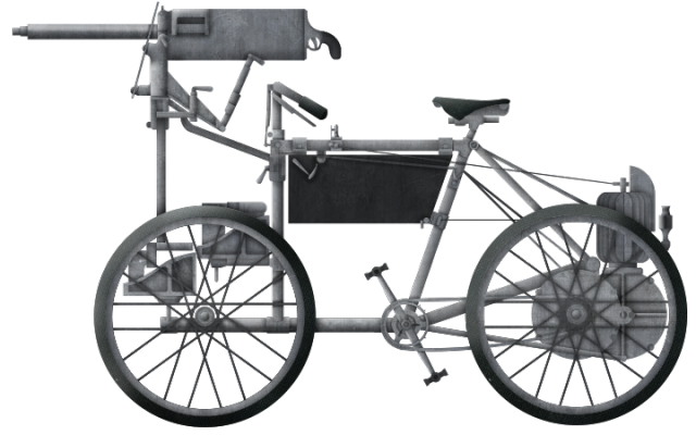
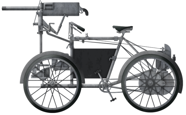
The French Polar explorer Dr. Jean-Baptiste Charcot (1867-1936) was known by Scott as the gentleman of the poles – a true gentleman explorer and adventurer. Seeing Shackleton take cars to Antarctica meant that Scott was looking for something better and in 1908 worked with Dr. Charcot on some Anglo-French motorized sledge experiments. Witnessed by troops from the 159th Chasseurs Alpins Regiment under Lt. Berger, two motorized sledges built by Dion-Boutton were tested alongside a tracked machine brought by Scott.

Dr. Jean-Baptiste Charcot testing his Dion-Bouton motorized sledge in March 1908. The large wheel-drive system is apparent.
Source: Aubert et al.

The French machines were based on an ash framed sledge with two runners curved up at the end like skis. Weighing 210 kg, it was powered by a 4 h.p. engine and could haul 500 kg at speeds of 4 to 8 km/h. Scott’s sledge, on the other hand, was a pair of metal frames with a single-cylinder engine at one end and the seat at the other. Running within the frame was a single-width steel track driven around two wide metal sprockets. The sledge was too heavy and Dr. Charcot’s lighter wheel-driven machine outperformed it. Dr. Chracot suggested to Scott he should adopt a larger 4 cylinder engine instead. Indeed, that is exactly what was to be fitted. Although Dr. Charcot also liked his own wheeled-machine, he was also of the opinion that once improved, Scott’s sledge would be of great use.

“From the experience gained at the trials, I believe this system, improved on the lines indicated in this report, would prove a most efficient tractor in the Antarctic”
From the Report of Dr. Jean-Baptiste Charcot on Scott’s motorised sledge.
Source: Aubert et al.

Scott’s tracked sledge during trials in March 1908.
Source: Aubert et al.

Dr. Charcot would eventually use one of these 200 kg French machines for his own work but Scott wanted a larger and heavier design to carry more material. He had also managed to get to see the problems with the Dion-Bouton sledges. They were not tracked and relied on simple skid plates and large wheels to gain purchase in the ice.

Captain Scott (left) and Jean-Baptiste Charcot (far left of right photo) with the motorized sledges built by Dion-Bouton undergoing trials at the Lautaret Pass, France at an altitude of 2,058 m in relatively un-Antarctic temperatures of just -12 C.
Source: jardinalpindulautaret.fr via Rouillon and Bignon Collection

It is important to note that, whilst the motor cars in the 1909 expedition had proven the concept of motorized haulage on Antarctica was at least possible, Scott seems to have understood the limitations of wheels and had a promising lead on an improved tracked sleigh. For his 1910 expedition, Scott brought with him the latest technical assistance in the form of motorized sledges but with tracks to gain traction on the snow and ice of the Antarctic.
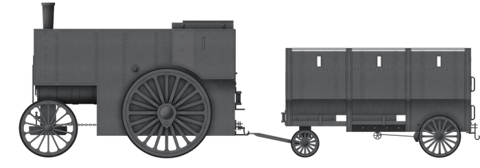
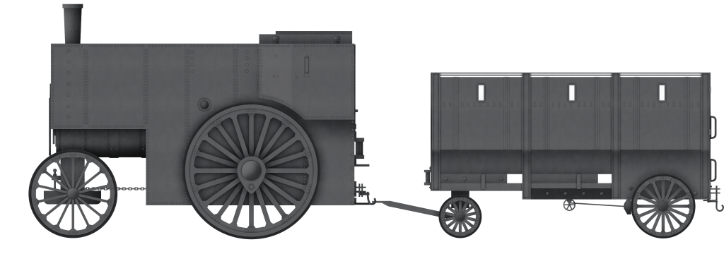
Design

The Wolseley Tool and Motor Car Company (later ‘Wolseley motors’), founded in 1901, constructed the motor sleighs in 1909 specifically for Scott’s 1910 Terra Nova expedition to assist in hauling materiel across the ice. The Wolseley machine was based on a design patented in 1908 by Mr. Belton Hamilton. Hamilton must have had some valuable technical knowledge and ability as, by 1919, he was a Major in the Royal Air Force and had previously given his occupation in patent applications as that of an engineer.

He was also upset by some of the publicity around the Wolseley vehicle in 1910 as he wrote to an eminent engineering periodical to complain that the vehicle should be described as the “Hamilton Motor Sledge Tractor”, as it was his design and was built and tested under his direct supervision. It may be that he actually sold the design to Wolseley Tool and Motor Car Company to manufacture, but looking at the patent leaves little doubt that the design is indeed his. A letter from Scott to Lord Howard de Walden in November 1911 provides additional information on the subject of the patent, and that Hamilton almost certainly sold the rights to Lord de Walden and, with it, much of the claim he professed about what it should be called.

Hamilton’s Patent for the track system used on the motor sleigh.
Source: British Patent GB10397
A completed motor sledge undergoing testing at the factory. Note that no seat has yet been added over the toolbox at the back on which the driver sits. The engine bay is not yet boxed in and the fuel tank is clearly on the top of the engine at this time.
Source: LeGros

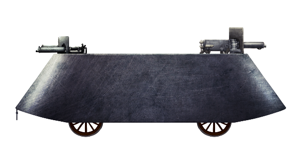
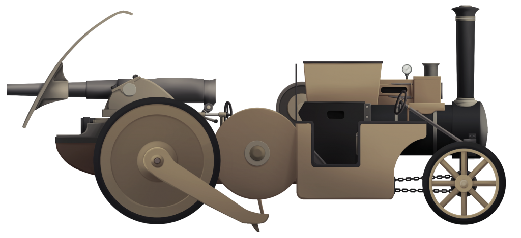
Framing for the vehicle was made from timber (possibly ash for its strength and flexibility) instead of metal like previously, and this timber was then clad in aluminum sheeting. The metal sheeting would prevent snow and ice from sticking to the wooden frame. Further metal cladding was provided around the engine for the same reason.

Underneath, the sleigh was covered with a sheet of thin metal to act as a snow shield and assist in floatation on soft snow and so nothing would catch on an obstacle.

The engine lay slightly ahead of center on the sledge, with the petrol tank directly above it. Although the method of fuel feed to the engine is not mentioned, the position of the tank would suggest that petrol was originally fed by gravity rather than by a pump. This changed later on, as the photographs of the sleighs in use in Antarctica clearly show that the fuel tank has been repositioned to be directly under the driver’s seat at the back. This would mean a fuel pump would have to have been added if there was not already one fitted. The toolbox, moved to make space for the repositioned fuel tank, was not omitted when this was changed – it was simply moved to the front. The addition of weight on the front likely assisted the tractive effort of the sleigh.

No cabin was provided for the driver of the sleigh, but he at least got to ride a vehicle instead of walking and, other than using the steering levers (no brakes were fitted to the sleigh), would have expended relatively little energy – right to the point where the sleigh becomes stuck. This would be a serious problem and men or another sleigh would have to be lashed to the stricken vehicle to haul it out.

The terrible conditions are evident here, where both motor sleighs are buried in a snowdrift. The repositioned fuel tank under the driver’s seat is readily apparent. Note the role of tracks in the right corner of the photo.
Source: Scott Polar Research Institute

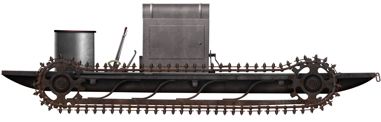
Tracks and Suspension

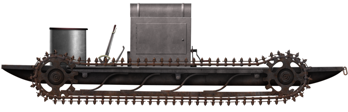
The tracks, described in the vernacular of the time as ‘chains’, were made from high tensile steel and fitted with wooden rollers. All of the bearing surfaces for the ‘chains’ were specially hardened by the supplier – Mr. Hans Renold and Company of Manchester.

The actual track plates, as we would think of them today, were known as ‘feet’ at the time and were bolted to the shoe which was pulled around the machine by the sprockets. The bolts attaching those pads or feet to the track had a pronounced pointed head to help dig into the surface to provide traction. Two spikes per link would be able to stab into even hard ice to provide grip. The same principle is still in use today with studded car tires.

A total of 37 links made up each track and a review of photos of the original vehicle shows a pronounced spud on the track plates for additional purchase in the ground. This is notable when the first tanks deployed by the British in 1916 had almost flat track plates with only a very small spud as a grip in the ground. This is even more noticeable on a small tank such as the Renault FT, a distinct lack of a built-in spud for soft ground – a lesson which could have been taken forward.

A suspension was provided on this tracked vehicle. Unlike the first British tanks of 1915 and 1916, on which the tracks were fixed in bearings attached to the hull side ran on the inside of the track link, the motor sleigh was both sprung and wheelless. The platform of the sleigh was actually sprung from the track units on each side by 4 elongated S-shaped springs connecting the bottom of the track frame to the body of the vehicle. As the track frames bounced along the rough ice, the vibrations would be absorbed by these large springs, producing a more comfortable and less tiring ride for the driver, but also less potentially damaging shock and vibration to the engine and transmission.

The second point to note is the lack of wheels. Small wheels can become easily clogged with mud, or in this case, snow and ice. The result is the same – more engine power needed to overcome the additional friction and a reduction in mobility. Wheels and the bearings for them are also heavy and the Wolseley sleigh avoids both problems by simply having the inner face of the track shoe run along the outside of a simple frame.

This is very similar in style to that selected by Lt. Robert Macfie for his 1914/1915 tank design and once more is something else that was not adopted on tanks. It is unclear if these sled-type track supports were the inspiration for Macfie but, given the publicity surrounding the expedition and his already pre-existing interest in tracked vehicles, it is certainly possible that he was aware of the vehicle and possibly influenced by it.

Cross-section of the Wolseley motor sledge. Note that the vehicle is facing left to right. Source: LeGros
Plan view of the Wolseley motor sledge, note that the vehicle is facing left to right.
Source: LeGros

The biggest issue with the tracks and suspension was track sag. Track sag is the phenomena of the tracks falling away from the wheels which run on it. When Colonel Crompton and Lucien LeGros were working on the first British tank ideas in 1915, this was one of the biggest problems encountered. Their work with a pair of Bullock Creeping Grip tractors connected together had a series of problems and one of the largest was this track sag issue. When a tracked vehicle crosses a gap, the track, being heavy, would fall away from the wheels above it unless there was a system to hold it in place either by some framework to stop it falling or with better track tensioning systems (or both).

On the face of it, track sagging away from the wheels is not a major problem as when the other side of the gap or trench is reached, the track is pushed back up onto the wheels. That is unless the vehicle is turning at the same time. If the vehicle turns whilst the track sags, the tendency will be for the tracks to come off. This was a serious problem in 1915 with tank-work and yet this was also clearly a potential problem in 1909/1910 with the motor sleighs, as photos show the track clearly sagging away.

Given the nature of the ground, crossing sastrugi for example for a vehicle in Antarctica again – this was a lesson on the tracks which could have been learned before the war and yet seemingly was not.

Seen here in 1915 on Col. Crompton’s articulated Bullock Creeping Grip tractors, the track is once more falling away (‘track sag’) from the wheels.
Source: IWM

Automotive

The engine was an air cooled 4 cylinder 12 b.h.p. Wolseley Petrol motor with cylinders arranged vertically and cast in pairs. Wolseley had been making a 12 h.p. petrol car and marine engine since 1905 and a 12/16 h.p. engine was being sold commercially at the time in one of their motor cars.

Lubrication was provided by means of a gear pump to drive the Filtrate brand special oil with an extra-low freezing point, so that it would not congeal. Starting was by means of a crank handle and could be assisted with the use of the exhaust jacket around the carburettor. This jacket was fitted with a small heating pan in which petrol or a similar fuel could be burned in order to preheat the carburetter.

Air cooling, given how incredibly cold it can get in Antarctica would, at first glance, sound sufficient. This was not the case, however, as forced air cooling was still required and this came from a fan located on the back side of the sledge’s engine box, drawing cold air from between the driver’s legs and the engine. Liquid cooling, such as using a radiator, was not impossible but obviously, the problems of using a radiator containing water is complicated by the fact it would be frozen, perpetually needing antifreeze and this added a lot of weight. Simple forced air fan cooling appeared to be sufficient but the engine was retained inside a large box on the chassis frame. Some contemporary images show this as a riveted or bolted metal box but it was actually just wood with some metal sheeting over the surface to stop ice sticking to it.

Poor positioning of the cooling fan directly inline with the engine also ensured that the majority of cooling was delivered to only half the engine, namely it only cooled 2 of the 4 cylinders. The first two cylinders, 1 and 2, would therefore receive the most benefit, whilst cylinders 3 and 4, those closest to the driver, received the least and led to problems of overheating. The bigger problem, however, was the lubrication. The extreme cold and the design of the engine meant that, even with the special Filtrate brand lubricant, the lubrication on the bearing surfaces of the engine was inadequate – this is likely the cause of the big-end bearings failing on one of the sleighs during use. It also indicates that the testing was not adequate before the vehicles were used.

Partially complete Wolseley motor sleigh with the bodywork left off.
Source: LeGros

Power from the engine was delivered through a two-speed leather-cone clutch gearbox with low gear and high gear forward only – no reverse gear was provided. From the gearbox drive, power was transmitted through a cardan shaft to a worm driven axle. The gear reduction was large, meaning a lot of rotations of the cardan shaft to produce a small movement of the worm gear which had “unusually large thrust bearings”. There was no differential fitted to the Wolseley rear (live) axle. Instead, a further clutch was provided by which the worm gear could be detached from the axle. This would take away all power from the rear axle and allow it to rotate freely – very useful for coasting down a slope. It was also the means by which the engine could be left running or idled without driving the vehicle, as no brakes were fitted to the sleigh. The front axle was undriven, as it was nothing more than a simple tube attached to the frame with a wheel on each end. The rear axle was likewise fixed to the frame.

“they consisted of two endless sprocket or articulated chains fitted with ‘feet’, passing over sprocket wheels, of which the after pair were driven by a petrol motor through a ‘2 speed gear box’, shafting and worm, and worm wheel”
From the Paper by Reginald Skelton (1872 – 1956) (Chief Engineer)
‘A Note on two forms of Motor Transport in the Antarctic’ presented 1914.
Source: Aubert et al.

The front axle was undriven and the teeth on the ‘sprocket’ at the front simply assisted the track to be retained on the wheel – it was not powered at all and those sprockets therefore only served as idlers. All power was, instead, transmitted through the sprockets at each side at the back and allowed the sled to move at 1.75 miles per hour (2.8 km/h) in low gear and 3.5 miles per hour (5.6 km/h) in top gear. In 1918, in an unusual description of its tractive ability, the engineer Lucien LeGros (1866-1933) described the vehicle as having been trialled at the factory, where “it was found possible to drive the machine over loose ashes without scattering them in any way” – a clear link to how he felt it would be good for operating on snow without throwing material into the air. The engine, therefore, provided sufficient power to drag the sleigh and load up a gradient of 1 in 2 (about 27 degrees).

Completed Wolseley motor sleigh showing a problem which would become familiar to LeGros in 1915 with tank development – track sag.
Source: LeGros

Fuel

In considering that the sledges had some serious technical shortcomings, attention has been drawn in the past to the possibility of the fuel being somehow faulty or contaminated. In a modern examination of samples of Shell Motor Spirit (S.M.S.) fuel of the period compared to a modern fuel, analysis by Volk and George (2008) considered the suitability of S.M.S. as a fuel. S.M.S. was one of a wide variety of early fuels for tractors which include petrol, distillate,* paraffin, heavy oil, and this type of straight-run** gasoline. Comparing S.M.S. to a ‘modern’ process petrol shows substantial differences in composition.

* ‘Distillate’ is a low-grade spirit, about 0.770 to 0.780 density.
** Straight-run means the simple distillation of crude oil whereas a ‘modern’ type fuel involves refining the various fractions of the products of distillation. The method of cracking to break hydro-carbons down into products with different boiling points so that they could be recombined to produce fuels of higher octane ratings did not start until 1913.

Despite the differences between the S.M.S. and a ‘modern’ process contemporary fuel, Volk and George concluded that the S.M.S. was a suitable fuel and likely did not contribute to the failings of the sledge. Instead, they placed blame on the failures on the inherent design of the engine being inadequate, listing three problems: flat-head engine design, a long exhaust run, and propensity for big-end failures.

The finished motor sleigh (still lacking a proper seat). Clear in this image is both the attachment at the rear for towing and also the heavily spudded and spiked track plates.
Source: The Engineer

Testing

The Wolseley-built motorised sleigh was built at the start of 1909. By March that year, it was undergoing cold weather testing at Lillehammer, Norway, followed by trials the following March at Lake Fefor, also in Norway. Here, it proved Dr. Charcot was correct in saying that this type of tracked machine could indeed provide potentially vital assistance. As such, three sleighs were ordered and built at a cost of £1,000 each (just under £200,000 each in 2020 values), although this was covered by one of the wealthy backers of the mission, like Lord Howard de Walden.

Of note is that Autocar magazine records 3 were also purchased by the German Polar explorer Oberlieutnant Wilhelm Fitchner (1877-1959) for his own expedition (The Second German Antarctic Expedition) of 1911 – 1913. His plan was very much similar to Shackleton’s, to cross the content from the Weddell Sea to the Ross Sea via the Pole. His expedition ended in a shambles and he never achieved his dream. From the available records, it does not appear that he took sleighs with him and, in light of the costs, may well have not purchased them at all.

Each machine was capable of hauling 3 tons (Imperial tons are slightly smaller than a metric tonne but the difference is negligible within the size of the loads discussed hereafter) of supplies. Three sleighs meant a total of 9 tons potentially, although obviously, the load would get lighter in the case of a polar trek, where food and fuel is expended. For reference, a Manchurian or Siberian pony could drag just 1,800 lbs. (454 kg) each and a dog 100 lbs. (45.4 kg) each at best for consumption of 10 lbs. (4.5 kg) and 2 lbs. (0.9 kg) of food each per day.* A single motorised sleigh, therefore, could haul the equivalent of 6 ponies or 67 dogs.

* Amundsen managed to extend this by feeding the weakest of his dogs to the strongest when he needed to in order to save food and extend range.

Wolseley motor sledge during testing on Lake Fefor, Norway, March 1910.
Source: Pinterest
Wolseley motor sleigh during testing in Norway, February 1910. Four sledges laden with men and items can be seen being towed behind the sleigh. Source: Autocar

The White War

Surviving against the brutal conditions in Antarctica was described by a member of Shackleton’s 1914 expedition as a ‘White War’, pitting man against the worst of nature in the form of endless ice and cold. In this war, the attempt to use cars had failed and so too would the attempt at motor sleighs, as neither could get past the Great Ice Barrier, the shelf of ice abutting the mountains bordering the great plateau. Covering some 250,000 square miles ( 650,000 km2) – an intimidating expanse of floating ice with few features, and no food or shelter, this barrier is today better known as The Ross Ice Shelf, although it is no less intimidating.

Motor sleigh in use in Antarctica. The 3,740 m high Mount Erebus – Antarctica’s only active volcano, is in the background. Source: Science Photo Library

Scott set up camp at a location known as Hut Point on Ross Island, close to where the modern McMurdo Antarctic station is located.

With a Camp at Hut Point, Inaccessible Island can be seen just across the camp from Erebus Bay with Glacier Tongue jutting out into the sound like a finger between the two locations. The route from Hut point to Corner Camp ran through a relatively windless area sheltered by the mountains to just off White Island, followed by the first big supply run to Bluff Depot (Shackleton). Scott set another large depot further South, called One-ton Depot. The decision of where to site One-Ton Depot was to prove fateful. From there, it was a straight run to the Beardmore Glacier. Map of Ross Sea Region, Department of Survey and Land Information, New Zealand with additional annotations by author. Unaltered: http://www.mappery.com/map-of/Ross-Sea-Regions-Map

Scott’s diary of the expedition recorded several key details on the operation of the motorised sleighs. All three sleighs were unloaded at Cape Evans (near to Inaccessible Island) in January 1911, along with all of the other expedition equipment. The sleighs proved very useful at this point unloading the array of building equipment, animals, and supplies for the expedition. However, during operations on the ice, one strayed onto a patch of thin ice and was lost to the depths of Erebus Bay. The other two machines were safe but used less to ensure no more mishaps.

Setting up these bases took months of work and preparation to be ready for the start of the Antarctic Summer in October. Come summer, came the attempt for the Pole and Scott’s rival, Amundnsen had set off for the pole a second time (his initial attempt failed) on 19th October via a different route.

Any attempt by Scott to set off at this time was hampered by the fact that one motor had broken down on 17th October, when the chain slipped away from the frames twice due to the rough ground. When the chain slipped off the frame the second time, the driver, Bernard Day, accidentally jammed open the throttle, causing the casing for the axle to split.

“I am secretly convinced that we shall not get much help from the motors, yet nothing has ever happened to them that was unavoidable. A little more care and foresight would make them splendid allies. The trouble is that if they fail, no one will ever believe this”
Scott’s Diary entry following the accident of 17th October.
Source: Aubert et al.

Despite this setback, the sleigh was repaired on the 20th and loaded back up for its journey on the 22nd. With the sleighs back in action, the British run for the pole was to begin on the next day, but was delayed by bad weather until the 24th, when the expedition set off into the interior. This meant a delay of at least a week due to these sleighs.

“I find myself immensely eager that these tractors should succeed, even though they may not be of great help to our southern advance. A small measure of success will be enough to show their possibilities, their ability to revolutionise Polar transport. Seeing the machines at work to-day, and remembering that every defect so far shown is purely mechanical, it is impossible not to be convinced of their value. But the trifling mechanical defects and lack of experience show the risk of cutting out trials. A season of experiment with a small workshop at hand may be all that stands between success and failure”.
Scott’s Diary entry 24th October 1911.
Source: Aubert et al.

The motor group set off in advance of Scott’s group, taking with them the two motor sleighs and as many supplies as possible. This would also provide assistance as the following party would have a nice clear set of tracks left in the snow to follow and supplies staged ahead of them. Scott, in the second party – the party which would make the run to the Pole, had the hardy Manchurian ponies to haul their sledges and a third group followed with the dog-hauled sledges.

Word from this leading group having problems with the sleighs came to Scott on 5th November revealing that although the sleighs had managed a respectable 7 miles (11 km) per day, problems were being had with the engine of Evans’ sleigh.

Extracts from Scott’s Diary Vol. 1
5/11/1911 Corner Camp
“A very troubled note from E. Evans (with motor) written on morning of 2/11/1911 saying maximum speed was about 7 miles per day… there are three black dots to the south which we can only imagine are the deserted motor with its loaded sledges. The men have gone on as a supporting party, as directed. It is a disappointment. I had hoped better of the machines once they got away from the Barrier Surface”

4/11/1911
“Picked up cheerful notices saying all well with motors, both going excellently” but within just 2 miles of finding that note Scott would be disappointed to read that the motors had, in fact, not been so excellent. He summarised the 29/10/1911 report from the advance party that “the surface was bad and everything seemed to be going wrong. They ‘dumped’ a good deal of petrol and lubricant.”

“Worse was to follow. Some 4 miles out we met a tin pathetically inscribed ‘Big end Day’s motor No.2 cylinder broken’. Half a mile beyond, as I expected, we found the motor, its tracking sledges and all. Notes from E. Evans and Day told the tale. The only spare had been used for Lashly’s machine, and it would have taken a long time to strip Day’s engine so that it could be run on three cylinders. They had decided to abandon it and push on with the other alone. They had taken the six bags of forage and some odds and ends, besides their petrol and lubricant. So the dream of great help from the machines is at an end! The track of the remaining motor goes steadily forward, but now, of course, I shall expect to see it every hour of the march”

6/11/1911 Camp 4
“We started in the usual order, arranging so that full loads should be carried if the black dots to the south prove to be the motor. On arrival at these we found our fears confirmed. A note from Evans stated a recurrence of the old trouble. The big end of No.1 cylinder had cracked, the machine otherwise in good order. Evidently the engines are not fitted for working in this climate, a fact that should be certainly capable of correction. One thing is proven; the system of propulsion is altogether satisfactory.”

Lashley’s sleigh had been lost to the icy water of Erebus Bay in January and now, at this critical trip out to lay supplies, the other two sleighs had failed in relatively short time. Instead of laying supplies out well into the Great Ice Barrier, the sleighs had in fact not got as far as Miona Bluff.

It is possible that the 3 tons of supplies which the lost sleigh was meant to carry had overburdened the other two but it is also clear that they had not been tested sufficiently beforehand. Scott had inadequate stocks of spares for the sleighs and no spare capacity with another machine. With both of his remaining sleighs now out of action, the first party would have to haul sledges of supplies by man power alone, laying out supplies as far as they could for Scott to follow.

Lieutenant Edward Evans (Second in Command and Navigator) (left) and Bernard Day (motor engineer) (right) standing alongside their motor sledges.
Evans reached the Pole with Scott and died on the return journey. Bernard Day did not go with the party all the way to the pole and survived the expedition.
Source: Scott Polar Research Institute
Bernard Day’s Motor sledge towing two sledges of supplies past the aptly named Inaccessible Island. The wheel on the back was for measuring distance travelled. Source: Scott Polar Research Institute

In his review of his mission Scott, despite facing death stoically like his men, knew his body and diary would one day be found and left a record of where he placed blame – misfortune and no mention at all of the motor sledges. A letter he wrote on 24th November to Lord Howard de Walden, even after the sleighs were lost, affirms Scott’s belief in them:

“This is written on our way South to tell you that though our motor sledges broke down there is nothing whatsoever the matter with the principle of propulsion of which you hold the patent – Had you seen them sailing over the snow down here as we did you would understand what I mean. The breakdown was solely due to the overheating of those wretched air cooled engines. I am quite sure there is a big future for tractor motors of this sort in Canada and other places. I therefore write most urgently to you to see the patents are all clear and safe in all countries. I think that Day our motor engineer will be returning this year and if he gets back before me I have asked him to call on you and explain the business… Hoping to tell you all about it some day”
Letter from Scott to Lord Howard de Walden 24th November 1911.
Source: Aubert et al.

Scott would never get the chance to fulfill the hope he expressed at the end of this letter. His expedition did indeed reach the Geographic South Pole but the supplies and energy expended and the delays involved took their toll. Amundsen got there nearly a month earlier and, on the return trip, Evans died at the Beardmore Glacier. Scott and the rest of the men nearly made it, getting as far as just 11 miles (17.7 km) from the major supply dump at One-Ton Depot – a two-day trip. Trapped by a storm and depleted by hunger, frostbite, and cold, he and his men met their end.

A Second Life – albeit brief

Despite the tragic deaths of Scott and the rest of his Pole party, Shackleton was already advanced in his preparations to return. When he did so, in 1914, as part of The Imperial Trans-Antarctic Expedition 1914 -1916, the goal was not to reach the South Pole, but to traverse the continent from the Weddell Sea to the Ross Ice Shelf via the Beardmore Glacier.

Shackleton would land at one side of the continent, at the Weddel Sea from the ship Endurance. A second-team would land on the other side of the continent, at the Ross Ice shelf, from the ship Aurora. The Aurora team’s task would be to lay supply depots for Shackleton and his men to live on on the second half of the journey from the Pole to the Aurora. Shackleton’s journey could have been a disaster when the Endurance was trapped and crushed in ice and the story of his men and the journey to safety across the Antarctic ocean in a lifeboat and crossing the unmapped mountains of South Georgia to safety are the stuff of legend.

Not knowing the fate of the Endurance team, the Aurora team battled the continent to lay out the stores, as required for Shakleton, but for which he would have no need. The story of survival for the men trapped apart from the Aurora is no less remarkable, living on the ice for years, surviving on seal meat in appalling conditions – those men were not rescued until 1917. It is within that story of survival that Scott’s motor sledges once more found a potential user.

The two broken motorized sleighs abandoned on The Great Ice Barrier by Scott’s expedition years earlier were seen as offering some promise to Captain Aeneas Macintosh for his task of laying out supply stops on the ice for Shackleton and his men to utilize. Each sledge of supplies was going to weigh in the order of 2 tons. That would have to be drawn by a dog team under normal circumstances the 13 miles (21 km) across the ice, yet if the old sleighs could be put to use, they could haul this material with relative ease.

Investigating the sleighs, they found that the fuel tanks still contained petrol. However, when the men tried to start the engine they found it pointless, as the leather clutch plate had burned out. Despite having very little food or fuel or other equipment landed from the Aurora, the men were fortunate that, among the small amount of material landed, there was a spare leather clutch plate.

The repair job was handed to Dick Richards and Irvine Gaze, who were hampered by having no proper tools to do the work. Nonetheless, they improvised what they needed and managed to remove the 33 bolts which held the clutch plate in place.

The replacement leather clutch had no holes in it for these bolts and once more these men had to improvise. Holes were cut in the new plate by heating nails over a blowlamp (also left over from Scott’s Terra Nova expedition) and using these to pierce the leather. Once reassembled, the sledges were operable but, despite all of this hard work, they discovered why they had been abandoned in the first place. Two expeditions had therefore tried the sleighs and both had been let down. They were simply unreliable and were abandoned for a second and final time. Neither sleigh is known to survive to this day and all three stayed on the continent for which they were built.

To Landships and Beyond

Robert Falcon Scott cast an enormous shadow as a name in Britain during the years through WW1. The stuff of Boy’s Own stories and meeting his end in a stoic and British way was used as an example to admire. To add to this, in the First World War, when tanks appeared in the public consciousness, a lot of people were eager to stake their claim to having some role in their development and the tracked motorized sleigh’s Scott used were already well known.

They were well known enough that they were mentioned in various papers and memoirs written by men involved in those first steps in tank design, men like Admiral Sueter and LeGros.

It is almost unimaginable that almost anyone could not have seen, read, or heard of Scott’s expedition before the War and these sleighs were a key part of it. Amundsen, a Norwegian, certainly knew of them, yet come 1915 and the start of track developments for a war machine, little was drawn from these sleighs. It is possible Macfie took some kind of inspiration from the sled-runner frames for tracks like his own design showed, but some of the lessons clearly had been forgotten in just a few years. The first track system fitted for a tank was the Bullock Creeping Grip chosen by Legros and Crompton and suffered badly from track sag. This was bad enough that it was replaced with a superior track system designed by Sir William Tritton from Messrs. William Foster and Co. Yet, even as he solved one problem (track sag), he failed to provide a sufficient spud in the track and these had to be provided later through various devices attached to the track plates. Underpowered engines, a lack of suspension, and unreliable machines were the bane of the first years of British tanks. Had Scott’s expedition succeeded, had the motorized sleighs proven the key to Britain reaching the South Pole, tracked vehicles may already have been in wider use, and the technology further advanced in those years between the Terra Nova and 1915.

As it is, they were seen more as a failure not to copy and, were it not for the name of Scott, would have been utterly forgotten.

To Strive, to seek, to find, and not to Yield

Line from Tennyson’s Poem ‘Ulysses’ Inscription on the memorial overlooking Hut Point erected to the men who died on the Terra Nova expedition 1913

Captain Scott’s Terra Nova expedition in 1910 had failed and he met his end infamous circumstances in March 1912. Tragically, the Scott team which made it to the South Pole died. Trapped by the harsh Antarctic climate in an unusually extreme storm which lasted 2 months – he and the remains of the Pole-team died just 11 miles (17.7 km) shy of ‘One Ton Depot’ – a supply point they had set up on their outbound journey. Scott was no bungler or careless or reckless amateur – he was a seasoned explorer and his team was well equipped. The narrowness of his death is enhanced by the tragedy of the failed motor sledges which, had they worked properly, could have got the team well ahead of schedule down the ice shelf with the supplies the members of his team so desperately needed.

Given the latter half of Scott’s tragic story, being caught in a storm just a day or two’s travel from One-Ton Dept and dying for want of supplies, this delay of a week undoubtedly contributed to the tragedy of the death of these men.

Little more was considered of the sleighs in the common imagination save for a movie using reproductions. In 1948, a film in the post-World War Two austerity of Britain celebrated the 50th Anniversary of Scott’s expedition. Titled ‘Scott of the Antarctic’, the film features the broken down motors on the Wolseley sleighs.

Scenes from the 1948 Scott of the Antarctic movie featuring the Wolseley motor sleighs. Note the small differences in the engine compartment to the real machines.
Source: IMDB

In the little over a century since the tragic death of Captain Scott and others on his expedition the novel technology which he helped pioneer has evolved well beyond the somewhat primitive Wolseley Motor Sleigh. Tracked vehicles have conquered every part of the globe including the poles, deserts, and mountains. They have even been envisaged at one time as being usable on The Moon and range in size from tracked wheelchairs up to giant industrial excavators.

The Wolseley Motor Sleigh, in fact, marks the appearance of one of the first commercial vehicles to use this form of propulsion technology and the fact that it is referenced by men who were notable just a few years later in the evolution of the weapon known as the tank shows its indisputably important place in the history of that machine.

One of Scott’s motor sleighs. If these had worked properly, the expedition might have been saved. Illustration by Yuvnashva Sharma, funded by our Patreon campaign.

Wolseley Motor Sleigh Specifications

Dimensions (L-W-H) ~3 m x ~2 m x ~1.5 m
Total weight: 750 kg
Crew: 1, Driver
Propulsion: Wolseley 12 h.p. Petrol (S.M.S.)
Speed 1.75 mph (2.8 kp/h) low gear, 3.5 mph (5.6 kp/h) in high gear
Armament Nil
Armour Nil
Haulage Capacity: 3 tons

Sources

ATSDR 4.1 Production of Gasoline. www.atsdr.cdc.gov
Aubert, S., Skelton, J., Fremont, Y., Bignon, A. (2014). Scott and Charcot at the col du Lautaret.
The Autocar. 19th October 1907. By Motor Car to the South Pole.
The Autocar. 24th December 1910
Automotor Journal. 4th December 1909. An Original Arrol-Johnson Design
Air League of the British Empire (1930). Industrial Britain. Vol. 1 The Albion Publishing Company, England
Bickel, L. (2001) Shackleton’s Forgotten Men. DeCapo Press.
British Patent GB10397. Improvements in and relating to Road Vehicles. Filed 13th May 1908. Granted 28th January 1909.
British Patent. GB1300264. Gun-mountings. Filed 27th February 1919. Granted 15th April 1919.
Hills, A. (2019). Robert MacFie. FWD Publishing, USA
Hills, A. (2020). Col. R. E. B. Crompton. FWD Publishing, USA
LeGros, L. (1918). Traction on Bad Roads and Land. Institute of Mechanical Engineers. Reprinted 2020 by FWD Publishing, USA).
The Engineer. 6th September 1907
The Engineer. 1st October 1909
The Engineer. 1st April 1910. Motor Sleigh for the British Antarctic Expedition
The Engineer. 22nd April, 1910. Motor Sleigh for Antarctic Work
Scott, R. (1910-1912). Diaries. Volume.I
Shackleton, E. (1914). The Heart of the Antarctic. Vol. 1. William Heineman, London
Sueter, M. (1941). Evolution of the Tank. Hutchinson, UK
Swithinbank, C. (1962). Motor Sledges in the Antarctic. Polar Record Vol.11, Issue 72, September 1962.
Volk, H., & George, S, (2008). The suitability of the fuel used for motor-sledging on Scott’s last expedition, 1910-1913. Polar Record July 2008, p276 – 277.

Categories
Pre-WW1 British Armor

Fowler B5 Armoured Road Train

United Kingdom (1899-1901)
Armored Roadtrain – 4 Built

The Second Boer War, fought by the British Empire against both the South African Republic and the Orange Free State from October 1899 to May 1902, was an enormous challenge for the British. Despite an enormous military advantage on paper, the British were fighting a war thousands of miles from their main bases of power in the UK and India, across the vast areas of South Africa over difficult terrain and difficult environmental conditions, ranging from the hot weather to the flies. The Boers, on the other hand, were fighting on land they knew well, able to supply themselves with what they needed and well supplied initially with modern German rifles. Highly mobile on horseback, Boer Kommandos were able to conduct highly effective raids on extended British supply lines and outmaneuver the British, who at the start of the war were not well prepared for a long and difficult fight against a well-motivated and skilled opponent. Having started the war poorly under the command of General Redvers Buller, the British soon got round to sending troops and supplies to the war and replaced General Buller with Lord Roberts, who was determined to protect his supply lines. In doing so, he was to produce probably the first armored self-propelled vehicle – nearly a generation before tanks first appeared in World War 1.

The Need

A key concern for Lord Roberts was ensuring that his overland supply routes were secured. There were railway lines, but these were hard to protect due to the distances involved and proved to be an easy target for sabotage, blowing up bridges, etc. Any other supplies had to be moved by animal-drawn wagon-trains and these were slow and extremely vulnerable to disease, attacks by wild animals and Boer bullets. As such, Lord Roberts was left with very long and tenuous supply lines.

Fowler traction engine hauling 4 unarmored wagons. Source: The Engineer

The Solution

In spring 1900, a solution presented itself – mechanical haulage of supplies. Supplies could be moved by means of steam-traction engines which required only fuel and water, and could haul much more useful loads without reliance on fixed and exposed railway lines. Of course, a traction engine in its own right is not bulletproof and neither is the driver, so the answer was obvious – clad a traction engine in armor plate.

To this end, Lord Roberts ordered 6 armored traction engines, each of which came with 3 specially designed armored wagons. Unarmored wagons could, of course, be towed as well if the supplies were not vulnerable, such as building materials or hay, but vulnerable cargo like ammunition and men could be carried behind the bulletproof plates. On top of this excellent utility, the engine was also sufficiently powerful to haul a pair of 6″ guns along with their stores, ammunition and crew. All told, a total load of 60-tons (61 tonnes) could be towed by a single-engine, a load made up by guns and wagons, whether armored or otherwise. Six such engines meant that Lord Roberts would have, at least theoretically, the ability to move around 360 tonnes of men and arms wherever he liked protected from Boer bullets.

The Designer

The engines for the vehicle came from the Leeds-based firm of Messrs. Fowler and Co. Ltd. but the person responsible for the design of the armor and of the carriages is not known for certain. Some unarmored but ‘special purpose’ wagons for South Africa were designed by the carriage works at Woolwich Arsenal, so it is possible that they were involved in that part of the work. One person certainly involved was Captain Nugent of the Royal Engineers. While attached to the War Office, his role was key in getting the project made, but whether or not he designed the actual disbursement of the armor and fittings, he was definitely responsible for the leather strips between the plates which stopped them from rattling. This might seem like a small thing but it does illustrate the closeness of his involvement in the project. The periodical ‘The Daily Graphic’ of May 1900 gives credit for the idea to Lord Roberts and the design to Cpt. Nugent. One name not involved in the design who was around at the time was Rookes Crompton. Crompton was working for Lord Roberts on the problems of moving supplies and guns involving traction engines and was even made a Colonel as a result of his actions in South Africa.

Investigations show that he was in South Africa with his electrical engineering unit at the time of these vehicles being made but, being an expert in road traction, he would certainly have taken an interest in these vehicles and would have known about them. He was also back in Britain before the last ones were sent, so he would also have the opportunity to examine them. Nonetheless, and despite some claims to the contrary (notably, Crompton himself never claimed that he assisted the project), he had no direct involvement in the design, although it is not to say that it might not have influenced his own later work on his Emplacement Destroyers in WW1.

Two views of the engine clad in armor showing the awkward position of the armored cab at the rear, but also the hold in the rear (bottom left below the door) where the winching cable would be spooled out. Source: The Engineer

The Engine

The traction engines for this task were manufactured by the firm of John Fowler and Co. Ltd., of Leeds, England, and were the ‘Super Lion’ model. Each Super-Lion weighed 17.5-tons (17.8 tonnes) and was fitted with a pair of rear wheels 7′ (2.13 m) high and 24″ (610 mm) wide.

Protection for these engines was provided by 4.5-tons (4.6 tonnes) of Cammell Laird and Co.’s 5/16″ (7.94 mm) thick bullet-proof armor plating formed into a large box-shape covering the whole of the engine. Other plates, for the bottom of the driving cab and the roof, were made from ¼” (6.35 mm) thick armor plate and the whole affair was fastened together by means of bolts and rivets. Messrs. Cammell Laird and Co. rated the vertical armor as providing protection against both the British Lee-Metford and the German Mauser rifles at a range of just 20 yards (18 m). Given the ranges at which many of the Boer ambushes were often taking place from over 200 yards (182 m) away, such protection could be seen as excessive and producing undue weight. As little as ¼” (6.35 mm) would probably have sufficed.

Despite the weight of the armor, however, these engines could still manage between 2 and 6 mph (3 to 10 km/h) on a good firm surface. For reference, without the armor, the engine was capable of up to 8 mph (13 km/h) in top gear with an operating range of 10-17 miles (16 to 27 km). The steam boiler, by virtue of its copper fire-box, was efficient and could burn whatever fuel might be available, such as wood, coke, coal or even dried dung. Its range was limited only by how much water and fuel it could carry. When using coal, the machine burned 7 cwt. (356 kg) of coal for every 30 miles (42 km) traveled.

Fully laden with armor, this vehicle was intended to weigh in at 17.5-tons (17.8 tonnes) with a 60-ton (61.0 tonnes) towing capacity, but was overweight at 22-tons (22.4 tonnes). As such, the load capacity was reduced to around 55 – 56 tonnes.

Layout

The design of the armor was somewhat crude, consisting of large flat plates bolted or riveted together on a vehicle not designed for such a thing. The drawbacks of weight were obvious but less apparent was the effect on the driver. Stood or sat at the back, behind the boiler, the driver hads, even under ordinary circumstances, a severely restricted view ahead. The armored cab afforded protection but it also further restricted his view and, standing on either side, he would only be able to see along each side of the engine through a small rectangular window. Additional windows were provided in the sides of the cab extensions and one in the rear of each as well, but nonetheless, the already poor visibility got substantially worse. The ordinary steering position for the driver was at the rear right and so, to see along the left side of the boiler, a mirror was fitted on the left-hand side of the cab so he did not have to move to see ahead.

The Wagons

The armored engine was only one part of the ‘road train’, the other were the carriages. These were not simply some wooden carriages clad in armor either. They were designed-for-purpose. Each carriage was mounted on 4 wheels, 2 small ones at the front, and a pair of larger wheels at the back. The sides of each carriage sloped gently out at the base before sloping back in again at an estimated 20° angle (from the vertical) towards the top. This sloping created angled sides which would help with deflecting bullets and allowed for men and stores behind the armor to be protected.

The armored wagon showing the angled sides and how they could be folded down to protect the stores carried inside. Source: The Engineer

The roof of the carriage was open, which allowed fresh air for the men. If the stores carried were vulnerable to fire, like ammunition, the sides could actually fold down to provide an armored roof. Loopholes in the sides and front of the wagons allowed for the men inside to fire their rifles out without having to expose themselves, meaning these carriages could also be used as a static blockhouse if required. No loopholes were provided in the rear.

This was not the end of the utility of the carriages either. Not only could they carry stores and/or men, they could also carry a field gun. The engine still had the ability to tow a gun, but with the use of a pair of angle-iron ramps at the back and opening the large rear doors, a 6″ howitzer or 4.7″ field gun could be hauled inside, although the 4.7″ gun would have the barrel sticking out due to its length.

Rear of one of the armored wagons for the road train showing the 4-part doors and method of loading a field gun into the back. The framework roof provided rigidity and ventilation and could be covered with a tarpaulin to keep off the rain and sun if required. Source: The Engineer

Production and Trials

Despite 6 engines being ordered, just 4 were built and fitted with armor, numbers 8894, 8895, 8898 and 8899 (note that 8896 and 8897 are missing from this sequence). Engine 8894 and 8895 were built in May and June 1900, respectively, and tested in the Leeds area prior to being sent out to South Africa.

Trials held in Leeds on 16th May 1900 were not well regarded. It was reported by observers from the trade press that this engine (presumably 8894, as 8895 was not finished until June per company records) entered a soft ploughed field with a slight slope towing its wagons and gun. Going downhill, it all worked fine, but on the way back it was unable to traverse the slope, tearing it up.

Fowler B5 Armoured Road Train undergoing road trails in or around Leeds, May or June 1901. Source: Hills

This was a significant problem and reflected very poorly on the off-road ability of the machine but was somewhat unfair as the engine did resolve the problem. To do so, it simply ditched the wagons and gun, drove up the slope and then used its powerful winching drum pulling a steel cable through the back. In doing so, the engine hauled up all of the loads up the hill, albeit incurring a delay.
Despite the relatively poor showing of the engines, 8894 and 8895 were sent out to South Africa in July to August 1900. The remaining two engines (8898 and 8899), were both finished in October and were sent out to December 1901.

Use

Despite the potential for hauling heavy supplies immune from Boer bullets, the engines saw little or no actual use as armored vehicles. Instead, these four engines (two more engines were delivered later unarmored) were stripped of their armor plating and put to use as ordinary traction engines in the service of the Imperial Military Railway (IMR). Had they been employed across the large open areas of the veldt (South African grassland), they would no doubt have provided a valuable addition to the supply situation during the war. The war continued into May 1902 but, by the time these engines had arrived, the problems of supply were being resolved. The Boers ability to operate was progressively diminished, albeit at a huge cost in terms of the numbers of men sent by Britain to tie them down.

Conclusion

The armored road train certainly had flaws, as it was slow and it was not good at climbing slopes, as illustrated by its trials in May 1901. What it did have, however, was the ability to move men and goods behind armor. Protected from Boer attacks, these could have been used to provide the supplies needed to pursue a lengthy and difficult war across wide-open areas. The end of the war, the problems with the engines, and perhaps the novelty of them as a new weapon of war meant that they never had the opportunity to be tested and evaluated properly in action.

There were other armored vehicles before and after the Fowler B5 running up to the start of World War I in 1914, yet no army was properly equipped with armored vehicles to haul men or guns at the start of the Great War.


Illustration of the B5 Armoured Road Train produced by Bernard Baker, funded by our Patreon Campaign.

Specifications

Dimensions (L-W-H) 19 9″ (6.05 m) long x 7′ 11 ½” (2.43 m) wide, 12′ 1 ½” (3.70 m) high (to top of chimney) 10′ 11 ½” (3.34 m) wheelbase
Weight 17.5 tons / 17.8 tonnes (unarmoured), 22-tons / 22.4 tonnes (armoured)
Crew 1 (driver) (possibly a stoker as well)
Armour 5/16″ (7.94 mm) on vertical plates, ¼” (6.35 mm) on other plates – proof against the British Lee-Metford Rifle and the German Mauser Rifle used by the Boers at 20 yards (18 m)
Propulsion 180 psi. (1,241 Kilopascals) boiler, 10 nhp (10 hp), composite spring-mounted type (copper firebox) producing 70/80 continuous Indicated Horse Power (I.H.P.) with 115/125 max. I.H.P. for short periods. Belt hp ranges from 30 to 48 (max.)
Speed 8 mph (13 km/h, unarmoured), 2 to 6 mph (3 to 10 km/h, armoured)

Sources

Hills, A. (2019). Col. R.E.B.Crompton. Pioneers of Armour Vol.2. FWD Publishing, USA
The Daily Graphic’ 18th May 1900
The Engineer 18th May 1900
The Electrical Journal Vol.34, 18th January 1901, 19th April 1901
Layriz, O. (1900). Mechanical traction in war for road transport. MArston and Co. London, UK
Nowers, J. (1994). Steam traction in the Royal Engineers. North Kent Books, Rochester, UK

Col. R.E.B. Crompton (Pioneers of Armour)

Col. R.E.B. Crompton (Pioneers of Armour)


By Andrew Hills
The foundations and principles of modern armoured warfare did not appear out of a vacuum, and nor did the machines of WW1 and WW2. Their development was full of false starts, failed ideas, and missed opportunities. Rookes Evelyn Bell Crompton was a pioneer in electrical engineering and road haulage who, by the turn of the century found himself in South Africa during the Boer War. Later, in WW1 his early work with the Landships Committee on tracked vehicles sought to break the stalemate of trench warfare. Although his tank designs never saw combat the work he started was carried on by other pioneers and helped to usher in a dawn of armoured and mechanised warfare. Buy this book on Amazon!


Categories
Pre-WW1 British Armor

Mann’s Armoured Steam Cart

United Kingdom (1901-1902)
Armored Tractor – None Built

At the turn of the 20th century, the British Empire was vast, and it had been embroiled in a long conflict in South Africa. This was happening at the same time as perhaps the greatest industrialization era ever known moving from an age of propulsion by animal power or the wind, to one of machines. Steam-power was still king and the first armored vehicles were starting to appear, although they were not quick to be adopted. Motor transports reliant on internal combustion engines were still relatively crude, heavy, and slow affairs as the technology for that type of propulsion was yet to reach maturity. This was the era of men such as Mr. Frederick Simms and his 1901/1902 War Car, and the armored Fowler steam-road-train ordered in 1900 for service in South Africa. It is perhaps the armoring of the Fowler steam engine which is the closest analogy and possible inspiration for Mann’s Armoured Steam Cart, even though the delivery of the design was different. Incongruous as it may sound today, in 1900-1902, the idea of a steam-powered traction armor carrying armor and weapons was a viable military idea, as proven by the Fowler engine, and Mann’s idea went one crucial step further – he proposed mounting a heavy cannon on his.

Simms’ War Car. Source: Engineering Times, June 1902

Inspiration?

In 1900, Lord Roberts, who was managing the British war effort in South Africa against the Boers, was having serious problems with his supply lines. The only mechanical transport available to Lord Roberts as an alternative to the vulnerable animal-drawn carts were railway lines, but these were also subject to attack and sabotage. Horse and bullock-drawn supplies could go places where the railways could not, but were much more vulnerable to attack by the enemy, and pests, and also required fodder. Boers could and did, with relative ease, raid and otherwise harass the wagon trains and interrupt supplies.

The solution for moving supplies to his forces over the huge open areas of the South African landscape was to add mechanical traction to his supply system, something not reliant upon fodder, not vulnerable to animal disease and, with the addition of armor, immune to the Boer bullets as well. Not only this, but the added advantage of being able to haul very heavy guns as well was a significant military advantage.

The result was an order for 6 engines from the firm of John Fowler and Co. Ltd. of Leeds. This firm produced a series of steam traction engines known as the ‘Lion’ series, ranging from the 7 hp ‘Little Lion’ up to the 10 hp Super Lion. Capable of towing up to 60-tons (61 tonnes), these 17.5-ton (17.8 tonne) Super-Lion engines were clad in armor up to 8 mm thick, rendering them proof against both British and German (the Boers used the German Mauser) ammunition at point blank range. The vehicle were slow, just 2 to 6 mph (3 to 10 km/h), but were limited in range only by the amount of water they could carry, as they could burn anything from coal, to wood, and even dried dung. Towing an equally protected train of armored carriages behind it, the Fowler engine rendered Boer ambushes of the supply lines effectively obsolete overnight. Or, rather, it would have done so if the war was not already winding down by the time they arrived. These otherwise very promising vehicles arrived too late to make any difference in the war and simply ended up having the armor taken off them and used for general traction duties instead. What they did achieve though was a very significant amount of publicity at the time and expanded the interest in armored vehicles. A rival steam traction-engine maker, Mann’s Patent Steam Cart and Wagon Company Ltd., from the same city (Leeds) as Fowler, could not have been unaware of this vehicle.

Fowler armored road-train during testing in Britain before being sent to South Africa 1900-1901. The engine is armored and it is hauling three armored carriages and a field gun. Source: Author

Mann’s Company

Originally formed in 1894 in Leeds by a pair of mechanical engineers, James Mann and Sidney Chatsworth, the firm was originally known as ‘Mann and Chatsworth’, before being reformed and renamed in 1899. The reason for this was the development of an agricultural cart powered by a small steam boiler. Mann then left Chatsworth in 1898 to pursue the exploitation of this design on his own, initially forming J.H. Mann and Co. and then Mann’s Patent Steam Cart and Wagon Company in October 1899, having been capitalised with ‎£25,000. A new plant was built and was operating by the end of 1901 producing his patent trucks.

British Patent GB21085 filed November 1900 (left) and US Patent US682262(A) filed February 1901 by Mann for his steam cart (right)
Mann’s Patent Steam Cart and Wagon Company’s new works at Leeds, as depicted in July 1901. The plant covered 4 acres (1.62 hectares) Source: Automotor

The firm was soon producing this very successful light steam traction engine adapted for a variety of uses, both agricultural and commercial. Even so, while it did not compete with the size or power of Fowler’s designs, Mann’s steam cart was smaller and more affordable, making it more practical for everyday use. As such, the vehicle found itself used for a variety of special roles and one of those was for field artillery.

The Field Artillery Version

The artillery version of Mann’s patent steam vehicle first appeared in a patent application, dated 27th April 1901, innocuously titled ‘Improvements in or in connection with the Mounting and Transport of Field Artillery’. It had a very clear goal. The intention was to replace the horse and limber team, which at the time was the standard method of moving a field gun around and had gone virtually unchanged in two hundred years, in the same vein as the Fowler. The idea was to use mechanical traction to replace vulnerable animals and, in doing so, present a smaller target to the enemy (than a long line of animals) and protect the vehicle and gun crew with armor.

Where the Mann vehicle differed substantially from the Fowler was that the Fowler was literally an armored traction engine, an engine to be used for its original purpose (heavy haulage) and clad in armor. The only armament on the Fowler engine was the crew’s personal small arms as it towed a gun and wagons with troops who could also use their weapons. The Mann went a step beyond this and was to mount the actual gun on the vehicle itself, producing direct haulage and a self-propelled field gun with armor protection.

Protection

No armor thicknesses were specified in Mann’s patent, as the design is not for armor but for the use of his vehicle as a platform for a gun. Nonetheless, he describes the shield for the gun and crew as being of:

“a suitable shape… fitted to the gun, turntable or carriage, so as to cover the gunners, and the motor and its attendants from a direct hit in front of the gun”

This was later expanded in description to clarify that the armor shield should be attached to the barrel, which was a poor choice for mounting considering that the gun was already mounted on a pedestal on the back. What this might mean in reality is almost certainly just that the idea was to provide bullet-level protection along the lines of a normal gun shield, albeit larger and curved. If the Fowler’s armor is anything to go by as a metric on which to assess how much armor this vehicle would have, then this would be around 8 mm thick.

A Mann’s steam lorry showing the novel flatbed. Source: The Engineer May 1901 and Automotor Journal, June 1901

Layout

The area between the side plates was intended to be able to be used for ammunition storage for the gun, but it is important to note that Mann did not add any armor to the vehicle itself, just to the gun. Other than the addition of ammunition stowage and obviously the pedestal for the gun and shield, the vehicle was little-changed from the original patent. The only significant change was the addition of a supporting gun tail attached to the rear axle on each side. This would be lowered or raised by means of a screw thread controlled by a large handwheel on the platform on which the operator sat.

The driver sat in the same position as he would normally in the front cab of the vehicle, with the boiler alongside his legs and the funnel at the front. Steering, just like the normal vehicle, took place at the front and was controlled by chains pulling to the left or right to guide the front wheels. This arrangement was very conventional for the time and would otherwise suggest that the vehicle would usually drive forwards. In battle, however, one particular problem with towing guns behind a vehicle or horse team was that the gun was always facing away from the direction of travel. Bringing the gun into action compelled the crew to brave enemy fire until they could unlimber and swing the gun around.. Mann’s design resolved this problem as his vehicle could be driven ‘backwards’ just as easily as it could go forwards, enabling it to drive with the gun and shield ahead of it facing the enemy. This is likely the reason why there was no other armor on the machine, as the very large shield over the gun served to protect the whole vehicle behind it.

Mann’s field artillery carrying steam cart from patent GB8654 April 1901.

With just two gears, it had a top speed in bottom gear of 5 mph (8 km/h), and in top gear up to a potentially bone-rattling 21 mph (34 km/h) on a good smooth road. Power was provided from a steam boiler with a pressure ranging from 18 psi (0.12 MPa) up to 20 psi (0.14 MPa), as the design of the short-type boiler and large firebox were progressively improved in the first decade of the 20th Century.

In 1905, the engine was described as producing a 7” (177.8 mm) stroke with a 4” (101.6 mm) high pressure cylinder and a 61” (1,549.4 mm) low pressure cylinder producing the same tractive power as a team of 6 good horses. Power from the boiler was delivered through a two-speed box to the rear wheels (3’6” to 4’ diameter / 1,041 mm to 1,219 mm and 5” / 127 mm wide) driven not by chains, as was common in that era, but by direct gearing. This was all available for the cost (in 1905) of £425, the equivalent of just over £50,000 in 2018 values.

Mann’s boiler shop at his Leeds factory circa 1905. Source: Road Locomotive Society

Conclusion

Unlike the Fowler armored engine, this design from Mann did not receive any contracts, even though his trucks otherwise sold very well. No further development of the idea was carried out and the design forgotten.

Mann’s Patent Steam Cart and Wagon Company was bought out in February 1929 by Atkinson Walker Wagons Ltd. of Preston and the new company changed name to Mann’s Steam and Motor Wagon Company, a sign in the shift from steam to internal combustion engines. Just a year later, in 1930, this firm was sold off to the firm of Scammell in London. The design was, especially for the first few years of the 20th Century, a good one. A large gun on a rotating platform protected by a large shield and all mounted together. Mann’s vehicle offered an interesting balance between speed and safety. While not being as fast as a galloping horse team, the steam engine could sustain its pace over long marches and boasted better suitability for the increasingly dangerous battlefields of the early 20th century.


Illustration of Mann’s Armoured Steam Cart produced by Andrei Kirushkin, funded by our Patreon campaign.


Specifications

Dimensions (L-W) 22’ 3” x 6′ 3″ (6.78 x 1.01 meters)
Weight 5 tons (5.08 tonnes) unladen
Crew Driver + gun crew
Speed 5 mph (8.0 km/h) bottom gear, 21 mph (33.8 km/h) top gear on good road
Armament Army field gun, small arms.
Armor 8mm, bulletproof

Source

The Automotor and Horseless Vehicle Journal, October 1899, New Companies Registered
The Automotor and Horseless Vehicle Journal, June 1901, Liverpool self-propelled traffic association third trials of motor vehicles for heavy traffic
The Automotor and Horseless Vehicle Journal, July 1901, The Mann Steam Wagons,
Commercial Motor, 8/9/1905, The Mann Steam Tractors, Carts and Wagons
Commercial Motor, 28/9/1905, The Mann Steam Tractors, Carts and Wagons
Commercial Motor, 26/3/1908, Mann’s Patent Steam Cart and Wagon Co. Ltd.
Commercial Motor, 22/6/1905, Motors and Tractors at the Royal Show
Engineering Times, Volume 7 , January to June 1902
Hills, A. (2019). Pioneers of Armour Vol.2: Rookes Crompton. FWD Publishing, USA
Pease, J. (2005). The History of Mann’s Patent Steam Cart and Wagon Company, Landmark Publishing, Ashbourne, UK
Road Locomotive Society. (1972). Mann’s Patent Steam Cart and Wagon Co. Ltd. catalogue. Reprint No.5 Road Locomotive Society, Cambridge, UK
US Patent 682262(A) Filed by James Hutchinson Mann – Steam-Vehicle for Common Roads, filed 18/2/1901, granted 10/9/1901.
British Patent GB13236 filed by James Hutchinson Mann – Improvements in or in connection with Road Traction Engines and Draught Road Vehicles adapted to be used therewith, filed 14/6/1898, granted 29/4/1899
British Patent GB8654 filed by James Hutchinson Mann – Improvements in or in connection with the Mounting and Transport of Field Artillery, filed 27th April 1901, granted 3rd April 1902
The Engineer, 31/5/1901 The Liverpool Heavy Motor Car Trials
The Engineer, 7/6/1901 The Liverpool Heavy Motor Car Trials
A Brief History of Yorkshire Patent Steam Wagon Co.

Categories
Pre-WW1 British Armor

Corry’s Land Ironclad

United Kingdom (1911)
Landship – None Built

In 1903, the author H.G. Wells wrote a short fictional story for the Strand Magazine titled ‘The Land Ironclads’. It was not, as commonly perceived, the first such idea for an armored land-warfare vehicle. James Cowen, for example, beat him to that in the UK by half a century, but Wells was certainly reflecting some of the thought of the time. It was, after all, just a couple of years since armored traction engines had been sent to war in South Africa and Frederick Simms’ War Car. There was also another name in Great Britain, almost forgotten by history, who pictured armored land-vehicles as shaping future warfare before WW1. Denied the platform of a well-read national platform like the Strand and a reputation like Wells, it is unsurprising that John Corry is a name alien to most. Corry though, despite his obscurity, featured within the investigations post-WW1 into who invented the tank and where these ideas originated.

John Anderson Corry was a young man from Leeds, in the north of England, and a shoemaker by trade, who fancied himself as an inventor. In 1910, he demonstrated a model of what he called his ‘aerial torpedo’ in various music halls across the country. A year later, in 1911 he invented a potentially far more lucrative idea, one he described as “a moving fort” and an “ironclad”, and in early November 1911, Corry was in his local newspapers describing his military inventions. Just a few days later, on 14th November 1911, he wrote to Winston Churchill, then First Sea Lord of the Admiralty, to describe his ideas for a land ironclad on tracks and other military inventions.

Number 61 Portland Crescent in Leeds
In November 1914, Corry’s letter to the War Office was sent via this property at Number 61 Portland Crescent in Leeds, presumably where he was living at the time. The address is seen here abandoned and dilapidated (the terraced house with the open window) seen here in January 1967 shortly before the area was demolished. The site is now part of Millenium Square. Source: Leodis.net via Leeds City Council

Letter to Churchill

With a small mention in a couple of newspapers which took some interest in his invention, Corry wrote (including the press cuttings) to the Rt. Hon. Winston Churchill who was, at the time, the First Lord of the Admiralty.

Part of Corry’s letter to Winston Churchill

In his letter, Corry took care to describe the machine in greater detail than was recorded by the newspapers extolling its virtues and suggesting that 200 of them should be built at an estimated cost of GB£600,000 (~GB£70 m in 2019 values). Across 200 vehicles, this means Corry was estimating the cost of each one at around GB£3,000 each (~GB£35,000 in 2019 values). For his part, Corry was not asking much, just GB£400 per annum (GB£46,000 in 2019 values) for this invention and was willing to wait upon his vehicle proving itself as viable before he even got any of that money. Even in 1911, Corry described his financial position as “rotten”, but that he had received interest in his ideas from a couple of unnamed South American republics. Whether that was true or not, his financial position seems to have remained poor.

Description

No picture of Corry’s model or design is known to survive, but there are descriptions, both in the newspaper articles of the time and more crucially in his letter to Churchill. This description, which survives in the Leeds Mercury of 10th November 1911, is of a vehicle weighing some 50 tons (50.8 tonnes) and “resembling a turtle”, suggesting an appearance not unlike that of Wells’ ironclads from 1903. Where it differed substantially from Wells’ ironclad though was that Corry was not suggesting wheels or ‘pedrail wheels’, but actual tracks.

Leeds Mercury, 10th November 1911

Armament

Corry’s ironclad was, according to Corry, and as reported in the media, to be armed with no less than four 4.7” (120 mm) guns and 8 Maxim machine guns. It is not clear which 4.7” (120 mm) guns Corry might have been considering, but it is probable that he was referring to a naval gun like the QF 4.7”, a 40 calibre gun capable of firing a 45 pound (20.4 kg) shell out to a range of around 12,000 yards (11,000 m). Each of those guns weighed around 2 tonnes, so four of them would be at least 8 tonnes or so just for the main guns. How they were to be arranged is also unclear as Corry merely describes the arrangement so that “three can operate on any spot at once”. If that is unclear, then Corry’s description of how the machine guns were arranged is more so. Corry described the arrangement of these 8 machine guns as allowing for “three firing fore and aft or 5 on either side”

Crew

Corry stated that his vehicle was to be crewed by around 30 men. Assuming two men per machine gun (2 x 8 = 16) and 3 per 4.7” gun (3 x 4 = 12), this would leave (12 + 16 = 28) a couple of men to fulfill the duties of commander and driver. Whatever arrangement Corry had considered is not made clear in either the newspapers or in his letter to Churchill.

Utility

Corry had not described a machine to meet the needs of the WW1 battlefield, those were still a few years away. Instead, he had described what was a prevailing concern in many quarters at the time, a seaborne invasion. Corry predicted that “such a thing patrolling our coasts… would undoubtedly prevent an enemy landing, or would wipe them out in an attempt to land”
In a little touch of hubris, Corry suggested his ironclad had the fighting potential of an army (infantry, cavalry, and artillery combined) of 2,000 men. More than this, Corry pictured his 200 land ironclads scattered around the coastlines of Britain. Spread around the coastline, 200 miles (322 km) apart they could retreat up to 16 miles (25.7 km) inland so as to be out of range of enemy naval gunfire supporting an invasion.

As this large vehicle would be inland and have to advance to make contact with an invasion force, Corry suggested a smaller version, faster than this large type, could close upon the enemy landings at high speed to make them hard to hit with naval gunfire. He provides no additional details of this smaller type of his machine, but logically it would be lighter, carry less armament, and be crewed by fewer men.

Mobility

No form of automotive power other than “two petrol engines of between 100 and 200 hp” was specified by Corry but he did state or rather ‘claim’ a potential speed of 18 and 20 mph (29 – 32 km/h). The smaller vehicle was estimated, again in a highly optimistic manner, to have a top speed of between 40 and 50 mph (64 – 80 km/h).

Not only was the vehicle fast, substantially faster than a man could walk, but also it was mounted on tracks. Corry’s design was described as having that pair of engines drive “two endless chains [i.e. tracks], fitted with massive ‘treads’”. By way of what the media described as “its peculiar construction”(presumably relating to its tracks), Corry stated that this vehicle was going to be able to climb walls up to 10 feet (3.05 m) high.

Corry did not specify what sort of tracks he was referring to, but 1911 was an interesting year for military tracked vehicles in the UK. The Lincolnshire-based firm of Richard Hornsby and Sons. had submitted three vehicles for traction trials for the army between 1905 and 1911. These trials were managed by the Mechanical Traction Committee (M.T.C.) and were generally successful in showing the potential of tracked vehicles and had, as early as 1908 and 1910, led to suggestions of mounting a gun and armor respectively. Whilst there is no information available on which to identify where Corry’s inspiration may have come from, these trials which took place just before his own claim could easily have helped to shape them.

Hornsby track system during trials in 1907.
Hornsby track system during trials in 1907. Source: Wiki

More Invention

Corry did not stop with the tracked ironclad either. He was also to claim the invention of a secrecy wireless telegraphy system although even by his own statement the range on his test model was just 28 feet (8.5 m) – certainly not very useful for the Army. In fairness, he did state that it could be used for long distance communication and the transmission of a secret and undetectable message even at a short distance by radio is not a minor thing. Even so, that idea was not taken up.

Nonetheless, that idea was not the end of Corry’s inventiveness. He also claimed the invention of a new design of propellor for boats which was more efficient and allowed for the somewhat improbable speed of up to 152 knots (175 mph / 282 km/h), a “sensible aeroplane”, and a multitude of inventions of gun sights for “guns of every description”. Disappointingly, these additional inventions went undescribed.

Post-Script

Corry missed out on any recognition or money post-World War I for his ideas. There had been, starting in 1918, a push to determine the who, what, where, and when of the invention of tanks and to award money for the ideas. Corry’s information was certainly made available to the commission in the form of his letter to Winston Churchill, but his idea was ignored. His case was taken up briefly on 29th November 1932 by Major James Milner (Member of Parliament for Leeds South East) in the House of Commons. Here, Major Milner pressed Mr. Duff Cooper (Financial Secretary to the War Office) on John Corry’s claim to be the first person to submit precise details of a ‘tank’ on 14th November 1911. Corry was unemployed by this time, had never received a penny for his inventions from the government. Major Milner raised the question over Corry asking Mr. Cooper:

“whether he is aware that Mr. John Anderson Corry…. was the first person to submit precise details of his invention of a tank, then described as a land ironclad, to the War Office… [and]… that to ensure secrecy in the national interest Mr. Corry did not make his invention public; that he has been unable to obtain any compensation and is now unemployed; and whether he will take steps to see that Mr. Corry receives appropriate recognition and compensation?”

Mr. Cooper’s reply was dismissive and also inaccurate:

“I am aware that Mr. Corry submitted on 14th November, 1911, a description of a land ironclad, and that his project was mentioned in the Press at the same time. There was no novelty in the principle of his proposal. Mr. Corry’s claim for compensation has been investigated by both the War Office and the Royal Commission on Awards to Inventors, and the decision that he is not entitled to any award has been consistently upheld.”

The idea that a tracked armored vehicle armed with heavy guns and machine guns was not a novel one in 1911 is wholly incorrect. Certainly it was not the first armored vehicle suggested to the War Office or even the first tracked vehicle offered, but it was assuredly one of, if not the first vehicle to be armed, tracked, and armored at the same time. Mr. Cooper’s response was either disingenuous or simply misinformed. Major Milner pressed Mr. Cooper further on the matter in the following exchange:

Major MILNER: Do I understand that, although it is admitted that this man was the first to submit the idea to the War Office, the War Office is not willing to consider the payment of some compensation to him?

Mr. COOPER: It is not admitted that he was the first to submit the suggestion.

Major MILNER: Is the hon. Gentleman aware that another military officer has been awarded a very substantial sum on the grounds that he was the first to submit this idea, and that the date was July, 1914, whereas the date of Mr. Corry’s submission was 1911?

Mr. COOPER: There was no novelty in the proposal put forward by Mr. Corry. As the hon. and gallant Member is probably aware, suggestions of this kind have been put forward for the last 2,000 years.

Major MILNER: If this idea has been common property for 2,000 years, why have the Government already paid another individual £15,000 as if the idea was something novel?

Mr. COOPER: Because he put forward a practical suggestion which really assisted the invention as finally made.

Conclusion

Corry’s letter is very revealing, not just for being an armed, tracked, and armored land vehicle designed to fight enemy forces but becasue who he wrote to. It was, afterall, Churchill who post-World War I received a lot of credit for thinking up the idea of an armored land vehicle. Whilst H.G. Wells’ Land Ironclads as a story was certainly known to at least some members of what was to become the Landships Committee, formed on Churchill’s ordered in February 1915, there is no proof that Churchill knew of them.

Here though, there can be no doubt. Winston Churchill received this letter from Corry in November 1911, over 3 years before he started trying to form a committee to discuss the problems of armored land warfare. For his part, Churchill should certainly have paid Corry’s ideas a little more attention. As far as is known from the records of the letter, Churchill did not even reply to Corry and in 1915 was suggesting his own ideas for an armored vehicle. It would not be until February 1915 that a track-based landship was decided upon in preference to wheels. Had Churchill paid more heed to Corry, engaged with him a little and possibly evaluated his ideas, it seems hard to imagine how an armored track layer would have to have waited until 1915 to be born.

This is not to say Corry’s idea was a good one. The armament was as ridiculous as it was excessive, the crew compliment huge, suggestive of a vehicle of a great size, certainly larger than could easily be accommodated on the road or rail network of the day. The speeds he estimated for his vehicles (large and small versions) were no less unrealistic given the state of tracked-vehicle technology in 1911, yet it cannot be ignored that Corry had seen a potential where others had not. He had tried to garner interest in his ideas through the media, and through the government and got nowhere. Even in 1932, well after the end of the war and with tanks in service with dozens of countries, Corry was denied any recognition for his idea – a most unfitting response to a clear vision for the direction land warfare would take just a few years afterwards. What became of Corry is unclear at this time, but the whole Burley Village area where he was living in 1932 was demolished in the mid 1950’s for redevelopment and, along with it, much hope for tracing one of the first minds in modern armored warfare.


Reconstruction of Corry’s Land Ironclad based on his description produced by Mr. C. Ryan, funded by our Patreon campaign.

Specifications – John Corry’s Ironclad (large type)

Total weight, battle-ready 50 tons (50.8 tonnes)
Crew ~30 men
Propulsion 2 x 100 – 200hp petrol engines
Speed 18 – 20 mph (29 – 32 km/h)
Armament four 4.7” (120 mm) guns and 8 Maxim machine guns.
Step 10 feet (3.05 m)

Specifications – John Corry’s Ironclad (Smaller type)

Total weight, battle-ready <50 tons (50.8 tonnes)
Crew <30 men
Propulsion 2 x 100 – 200hp petrol engines
Speed 40 and 50 mph (64 – 80 km/h)

Sources

UK National Archives records R1940, Papers relating to Landships
Leeds Mercury newspaper, 10th November 1911
Daily News newspaper, 8th November 1911
Leeds City Council leodis.net
www.leodis.net
Hansard. (1932). Parliamentary Debates: Official Report Volume 272.

Categories
Pre-WW1 British Armor

Simms’ Draisine

United Kingdom (1901)
Draisine – 1 Built

Frederick Richard Simms (12/8/1863 to 22/4/1944) is best known in military terms for the rather silly looking ‘Quadricycle Motor Scout‘ of 1899 despite founding a very successful engineering firm in his name. He had been inspired, at the turn of the 19th century, by his knowledge, expertise, and experience in motor vehicles to seek out new business ventures and military contracts were a good source of income if one could be obtained.

Mr. Frederick Richard Simms, Photo: Autocar Magazine
He had been born in Germany in August 1863 and educated in Berlin where he met the famous German engineer Gottlieb Daimler. Soon after obtaining a patent from Daimler for his high-speed petrol engines he had moved to London where he founded Simms Motors to make use of this engine. By 1896, he had become a consulting engineer to the newly formed British Motor Syndicate (BMS) and, the following year (1897), a founding member of what is now known as the Royal Automobile Club of Great Britain.
In 1899, he had tried his hand at a military venture combining a small petrol driven quadricycle (known as the ‘Motor Scout’) fitted with a small bulletproof shield and a .303 caliber Mark IV Maxim machine gun and despite proving as a concept that a small machine could be used to move a machine gun around with a high degree of mobility, he received no orders.

Simms armored draisine on rails showing the same type of machine gun and mount as used on his motor scout of 1899. Photo: Royal Automobile Club collection
The Second Anglo-Boer War was underway by the end of 1899. Fresh from trying his hand at the Motor Scout, Simms turned his eye to helping the British Army. They had entered that war ill prepared for the type of fighting they faced. Large swaths of territory and a highly mobile enemy were hard to pin down and restricting their movements was going to be key to winning the war. Eventually, to pacify the Boers, the British constructed long lines of defenses with blockhouses etc. and it is perhaps because of this that Simms unveiled (in his trademark bowler hat of course) his draisine design to assist in patrolling the railways.


Illustration of Simms’ Draisine by Bernard ‘Escodrion’ Baker, funded by our Patreon Campaign.

A very crowded Simms armored draisine on rails with no less than 6 men aboard. Photo: Royal Automobile Club Collection
There is little information available on his design which is known as a draisine. A draisine is simply a light auxiliary rail vehicle for moving equipment or people around and the purpose of this one was to move a crew and a machine gun. The diminutive vehicle consists of a rounded ‘bathtub’ shaped armored body which, if it is similar to his subsequent War Car, would be approximately 6mm thick bulletproof steel. Riding on four wheels on the railways and driven by a small 7hp water-cooled petrol engine connected to a three-speed Panhard gearbox the draisine was capable of a respectable 30mph (48 km/h). The machine was open topped and fitted with a single .303 caliber Mark IV Maxim machine gun of the same type (and same shield ) as that from his Motor Scout. Simms envisaged the machine as fulfilling the role of a scout, patrolling the railways and deterring raiders and although it only mounted this single machine gun for his publicity was also to mount a one-pounder pom-pom gun and a searchlight.
Despite managing to cram in 6 men for a photo opportunity at one point, there is clearly no room for a crew of 6 and the suggested compliment was four men.
It is not known what happened to the Simms draisine but he did not patent it and it does not appear to have received any production orders. The photos of him show the machine being tested on a section of line on the north shore of the River Medway and the device is rumored to have been sent to Nairobi. Despite his best intentions his machine was to have no effect on the Boer War or any other war for that matter. Simms was on failure number 2 in terms of military machines although his civilian business was successful. This was not the last military invention from Simms though, more was to follow.

Specifications

Crew Est. 2 – 3
Propulsion 7hp petrol
Armament 1 x.303 calibre Mark IV Maxim machine gun, 1 x one-pounder pom-pom gun
Armor Est. 6mm steel.

Resources & Links

Royal Automobile Club of Great Britain
Autocar Magazine, 11th November 1916
War Cars, David Fletcher

Categories
Pre-WW1 British Armor

Simms’ Quadricycle Motor Scout

United Kingdom (1899)
Scout Vehicle – 1 Built

The name Frederick Richard Simms (12/8/1863 to 22/4/1944) probably means little to anybody now as his most famous invention, his machine gun armed four wheeled bike, is commonly seen on the internet and in books usually for the purposes of humor. The man and his designs are quite real though and were no joke at the turn of the 20th Century. The modern repeating machine gun had only just started to enter common service with some armies and motor cars were a rare sight. Armored warfare at that time was so new terms we use today like ‘armored car’ had not entered the lexicon. The ‘tank’ was still more than a decade away. Frederick Simms was a pioneer of blending these emerging technologies of mobility and warfare.

Mr. Frederick Richard Simms, Photo: Autocar magazine

Frederick Richard Simms was born in Hamburg, Germany in August 1863 to a British father and German mother. He befriended Gottlieb Daimler and moved to London establishing Simms Motors and in 1896 became a consulting engineer to the newly formed British Motor Syndicate (BMS) in 1896. In 1897, he also became a founding member of what is now known as the Royal Automobile Club of Great Britain, and in January 1898 submitted a patent for his first design of military application, namely “Improvements in Armouring or Protecting Surfaces against the Action of Projectiles” which may have been connected to his later ‘War Car’.

The Motor Scout Quadricycle

The first attempt from Simms to design a military vehicle was very similar to the design of Mr. E.J. Pennington. The quadricycle based ‘Motor Scout’ as he called it, is Simms’ most famous creation and it was finished in March 1899. Admittedly, in hindsight, the image of the bowler-hatted Mr. Simms on this machine is ridiculous but in the context of 1899 it is less so. Queen Victoria was still on the throne, the lessons from the slaughter of World War One were nearly a generation away and no nation could claim experience in armored warfare. Simms was taking the new “light Maxim type” machine gun and making it mobile on a cheap and simple 4 wheeled commercial quadricycle.

Mr. Simms mans the Scout’s main gun in 1899 while it is on display at Richmond Park. Photo: Autocar magazine

Most sources cite the quadricycle as being a de Dion Bouton but it appears to actually be a license-built model 1898 machine made by the firm of The New Beeston Cycle Company of Coventry which was owned by Harry Lawson at the time. The frame, despite having pedals, was also provided with a small 1.5 hp petrol engine which could drive the rear wheels via a chain and sufficient fuel for a 120 mile (193 km) range at 18 mph (29 km/h) or with a double tank for 240 miles (386 km).

The wheels themselves appear to remain the standard pneumatic road wheels rather than any kind of protected or bulletproof tire.

Simms Motor Scout of 1899 on display at Richmond Park, Photo: Autocar magazine

Armament

The machine gun, a .303 caliber Mark IV Maxim was fitted with a small bulletproof shield and, despite the pose with the gun ‘in use’ from the riding position, it was actually intended to be more of a mobile mounting from which the gun could be dismounted for use. The quadricycle frame was then to be reused as a frame on which to place a litter to evacuate wounded troops or just for moving supplies; a concept far less ridiculous than the famous photograph would suggest. If the rider wanted to use the machine gun he certainly could, it was arranged so as to not interfere with the view of the rider. Within the frame and within reach was an additional store of 1000 rounds of ammunition. The ammunition would be mounted on a rail below the machine gun between the front wheels.

1899 Patent for the Simms Motor Scout. Photo: Public domain

Conclusion

Despite having produced a working example of his patented Motor Scout, the machine did not sell. The concept did sell, however, as other bicycle and motorcycle-based units with machine guns mostly for experimental purposes were formed. The fate of the Motor Scout is unknown but likely it simply got turned back into a quadricycle and sold off. Frederick Simms might not have won any contracts for his idea from the Army but he didn’t give up and he followed this small design with a much bigger design, a War Car.


Illustration of the Motor Scout based on the original line-drawing

Illustration of the Motor Scout based on the historical 1899 photos added with Mud-Guards.

Both of these images were illustrated by Bernard ‘Escodrion’ Baker, and were funded by our patreon campaign.

Specifications

Crew 1
Propulsion 1.5hp Petrol
Maximum speed 18 mph
Range 120 miles standard or 240 miles extended
Armament 1x Mark IV Maxim .303 machine gun (1000 rounds)
Armor Single Bulletproof Sheild

Links & Resources

Autocar Magazine 26th August 1899
Landships.com
Simms War Car – Additional Notes, BT White, landships.info
Allgemeine automobili-zeitung May 1902
Patent GB22610 filed 12th October 1896
Patent GB2297 filed 28th January 1898
Patent GB7337 filed 26th March 1898
Patent US641897 filed 20th October 1898
Patent GB5885 filed 17th March 1899
Royal Automobile Club of Great Britain
Journal of the Society of Arts, 14th July 1899
The Motor Car Journal, 12th April 1902
Motor World, Volume 2, April 1902
Engineering Times, Volume 7 , January to June 1902
Autocar Magazine, 11th November 1916
Early Armoured Cars, E. Bartholomew
Early Armoured Cars, Maj. Gen. N. Duncan
War Cars, David Fletcher
Coventry’s Motorcar Heritage, Damian Kimberly

Categories
Pre-WW1 British Armor

Cowen’s Locomotive Land Battery or Devastator

United Kingdom (1854-1862)
War Machine – Drawings and Model Only

It is commonly accepted that the tank was invented by the British in WW1 as a means to break the stalemate of trench warfare. What is not well known is the number of armored vehicles designed and used which predate the appearance of a modern tank.
There were many ideas from ancient times to the medieval period for covered wagons or protected carts, but none of these machines had the fundamental element of a modern fighting vehicle: an engine. One of the first vehicles combining both protection for the crew, offensive weaponry, and an engine was designed not in the early years of the 20th century, but in 1855.
The designers, Messrs. James Cowen (of Greycoat Street, Westminster, London) and James Sweetlong (Earl-Street, Westminster, London) submitted their design requesting a Patent on the 3rd April 1855 under reference number ‘747’.

Description

There are various descriptions of this machine available in both contemporary and more modern sources, all of which hint at what the machine really looked like.

“This invention consists in forming a large land battery, running on wheels and driven by steam. To the framing of the battery and at right angles to its length, are fitted strong and powerful blades turning upon a hinge joint, so as to lie close to the framing when not in use, and to be instantly thrown out when required by the artillery-men or persons inside the battery, ‘the effect being to mow down any troops that come in contact with or near the battery”

– Mechanics Magazine 1855

“Consists in an armour clad locomotive land battery propelled by steam power. The engine and boilers are placed below the floor of the gun-room, the engine room being in the middle. The vehicle runs on five wheels, the fifth being situated centrally at the front to act as a guiding wheel”

– Abridgments of specifications (Patents), 1855-1865

“A massive framing is proposed to be fixed on five broad wheels. Upon this framing ordnance is mounted, and loop-holes may be made in the sides thereof for riflemen. The carriage is to be driven by a steam-engine”

– Abridgments of specifications (Patents), 1859

“In 1855 James Cowen took out a patent (No. 747) for a ‘Locomotive Battery for Field of Battle with steam engine.’ It held 14-pdr. Carronades and the framing had strong, powerful blades (scythes), hinged when not in use, to mow down any troops that came in contact with it. The cover was of hardened steel, serrated or formed in sharp angular projections, to shatter any shot that may strike them. This is a direct opposite to the ‘glancing surface’ which was one of the noticeable features of the best defensive armour and is still observed in the helmets of 1915 pattern and the battleship turrets of the Navy. The shape of Cowen’s covering, very similar to that of Leonardo da Vinci’s, was good, and would probably have been more protective if it had been left smooth. Cowen took out several patents for agricultural machines, but does not seem to have taken out any protection for his experimental war-cart”

– JSAHR, Volume 16, Summer 1940

“In 1855 James Cowan [sic: Cowen], a wealthy philanthropist, took out a patent for a steam-driven ‘locomotive land battery fitted with scythes to mow down infantry.’ It was a four-wheeled armoured vehicle armed with guns, and ‘looked like a huge dish cover on wheels.’ It was rejected by Lord Palmerston as being too brutal for civilized warfare”

– The Conduct of War 1789-1961 quoting ‘The Tanks’ by B.H. Liddle Hart 1959

‘This invention consists of an improved locomotive battery to be used in the field of battle, and is so constructed as to exert a most destructive force against the enemy, while protected from damage in return”

– Tale of the Next Great War – IF Clarke, 1995

Just like the descriptions provided by some authors, there have also been various interpretations and artist’s impressions of the machine, and they are reproduced here to examine how so many different interpretations exist and how they came about.

‘Cowen’s Battle Car, 1855’ looking like an upturned dish cover. Just four wheels shown. Photo: JSAHR, Vol. 16, Summer 1940

Mostly correct except the guns which are on the wrong deck and the shape of the skirt is wrong. Source: Unknown

This vision of the machine is clearly drawn only from a description as the spiked surface and fifth wheels are well described but the overall shape is completely wrong. Photo: Voices Prophesying War, 1966

Almost certainly just copied straight from ‘Voices Prophesying War this is a very well drawn vision of the machine but completely wrong. Photo: www.tankinfo.ru, 2012
The real machine, both in looks and description, is somewhat different, however. Apart from the version with the spiky roof, most of the drawings get the rough impression of the machine correctly and some of the descriptions get some or all of the features, but none of them are conclusive or complete. Thankfully, not only has Cowen’s original submission from 1855 been located, but also the poster and letters Cowen sent to Lord Palmerston (British Prime Minister 1855-1858).

The Real Machine – 1855

In the original patent of April 1855, there is no picture or outline which might account for some of the variance in the images for the vehicle over the years. The vehicle is well described though, consisting of a massive and sturdy framework onto which five broad wheels are mounted, with one positioned centrally at the front of the vehicle to act as a guide wheel. A further note on the wheels is that to “assist the progress of the battery over yielding ground” projections or cogs could be fitted.
The outside of the machine is covered with “stout plates of hardened steel” which have their outer surfaces serrated or shaped to form sharp angular projections from the body which would serve to shatter projectiles hitting the armor. No thickness of armor is specified, but the overall shape of the vehicle’s body is elliptical.
Propulsion for the machine is by means of a steam engine located in a recess in the flooring of the chamber. The boilers for the engine are placed below the flooring of the gun room and along each side of the recess forming the engine room in such a way as to permit easy access.
Armament for the machine was provided by “14lb. carronades , or other suitable sized guns” as well as one or more steam-powered guns using steam from the boilers to propel shot. Further offensive capability is provided by means of multiple port-hole type apertures around the circumference of the gun deck along with small holes for observation. Finally, and most infamously, fitted to the framing and at right angles to it are “strong and powerful blades, turning upon a hinge joint so as to lie close to the framing when not in use” which could be thrown out by riflemen when needed to mow down troops too near to the battery – though there is no mention of them being spring loaded.

The 1862 Machine

In 1862, Cowen submitted more information and the only reliable image of the machine in correspondence to Lord Palmerston. For these letters, he had added some additional information to his 1855 outline providing us with more insight into what he had envisaged 7 years earlier.
The design, according to Cowen, was a “shot and bomb-proof steam engine” able to travel at over 20mp/h [32km/h] and which could be adapted or modified to carry weapons of any calibre or quantity that may be desired. The machine had two levels: an upper platform of the vehicle constructed so as to form a continuous platform of rifled barrels able to fire a ‘sixty ounce bullet’ per minute with the adventurous claim of a range of two miles. Sixty ounces is 3.75 pounds (1.7 kg) which suggests something like a 4-pounder gun with a diameter in the region of 3 to 3.2 inches (76.2-81.3 mm). The Battle Car’s image, as drawn, would show 12 of these guns arranged around the circumference of the machine. Alternatively, this could just be substituted in whole or in part for loopholes for riflemen to fire from.

Cowen’s own rendering of the invention from his submission to Lord Palmerston 1862. Note that the vehicle is seen traveling left to right. Photo: Cumbria Archive Services
The blades on the sides were now knives or swords and described more thoroughly as:

“projecting from the axles of the wheels of the Battery are revolving scythe-shaped knives or swords – which, without the aid of steam armament but combined with the irresistible power of the Ram formed to work in both ways – would effectually annihilate Cavalry, Infantry, and crush batteries of Artillery”

– James Cowen, 1862

Cowen envisaged the machine not just for land use but also for naval use, stating that it could be used as a naval ram as well by simply wheeling it onto a “shot-proof pontoon adapted for it”. From the image he provided in 1862 and the contemporary descriptions, we see a large machine supported on four large spoked wheels with a fifth smaller wheel at the front to assist with steering. The body of the machine is armor plated mounted to a very substantial framework internally combining to protect the occupants therein from enemy fire.
In the 7 years since his initial application, the design had changed slightly. Gone was the mention of serrations or spikes, alternatively they are simply too small to show in his image. Gone were also the 14-pounder carronades, replaced with smaller guns (approximately 4-pounders, see above). The basic shape and arrangement of engine, wheels, and fighting chamber remained the same, however.
Cowen reflected on his design in 1862 reminding Lord Palmerston of his personal meeting at Palmerston’s house in Piccadilly. The vehicle “which was named by the late eminent Philanthropist Robert Owen, ‘The Peace Maker’”. His design had been referred on by Palmerston to the War Office and Board of Ordnance at Woolwich, putting pay to subsequent mythology about Lord Palmerston rejecting the design as inhumane or ungentlemanly.
Cowen reminded Lord Palmerston that he had been given permission, in talking to the War Office and Board, to use Palmerston’s name as a reference. He further reminded Lord Palmerston that the Prime Minister had himself remarked “as the machine was to Supersede Soldiers, Armies fought everywhere” as some measure of the validity of his proposal. Palmerston was clearly then not rejecting the idea and, whilst maybe not fully endorsing it, certainly thought it worthy to have referred to an expert body for consideration. The permission to use his name as a reference for the invention could only have served to assist Cowen in his endeavors.
Cowen himself states that it was not Lord Palmerston who rejected the design, but the “washed-out Old Women and Senile Old Tabbies at Woolwich” and specifically Lord Hardinge (Commander in Chief of the British Army 1852-1856) who “had plenty of experience with guns and the firing of them, but … did not understand engineering”.
He had wanted GB£2000 (about GB£226,000 in 2018 values) for the designs and plans to cover what he claimed he had spent on the patent fees and the engine model which would explain the presence of Mr. Sweetlong as the engineer and model maker. Having been rejected in 1855, Cowen claimed that his model maker simply left the country with the information and model and submitted them “without my knowledge or sanction” to the French, and then to both the Confederate and to the Federal States of America.
He was therefore trying to gain interest in his vehicle once again, not from the angle of the design on its own merits, but because, as he was claiming, the machine was now known to potential strategic adversaries, such as Louis Napoleon of France, the United States (both North and South), and even Russia, implying that Great Britain should have to keep up. This 1862 poster campaign (he claimed to have had 20,000 printed) and letter writing was to no avail.
He had already significant financial problems claiming to have been wealthy and listing his occupation as a Medical and Political Reformer (in 1862), but had already been in debtors gaol on and off since at least July 1855. At one appearance at court in September 1855, he was named as the inventor of a “locomotive Land Battery or Devastator”. He claimed his prison worries were as the result of complaints from the Church for him distributing GB£30 (about GB£3150 in 2018 values) worth of food and cash to the poor “in mockery of the Deity of the Fast Day” with court costing him another GB£1000 (about GB£105,000 in 2018 values) on top on his claimed GB£2000 (about GB£226,000 in 2018 values) expenditure on his patent and model.
By his own admission, Cowen never made a farthing (a quarter of a penny) from the invention. James Cowen, occupation given as ‘Dispenser of Drugs’, was declared insolvent (Case no. 65,433) by the Court at Lincoln’s Inn, London on the 17th November 1855. His financial troubles were finalised in October 1859 when “James Cowen, known as James Cohen, and as Dr. J. Cower, formerly a Prisoner in the Debtors’ Prison, White Cross-street, London, of No.3, Grey Coat-street, Westminster, and No.8, Broughton-place, Hackney-road, then of No.3, Grey Coat-street, aforesaid, then a Prisoner in the House of Correction, Cold Bath Fields, Clerkenwell, all in Middlesex, and of No.3, Grey Coat-street aforesaid, and now of the latter place describing himself as a Medical and Surgical Reformer, and Dispenser and Dealer in Drugs and Chemicals, late an out Pensioner of Chelsea Hospital” when by indenture he assigned all of his remaining goods, stock in trade, furniture, effects, estate, and remaining debts to Matthew Dodds (Forgeman), Joseph Cowen (a Grocer, and presumably a relative), and John Cowen (also presumably a relative), all from his hometown of Crook, County Durham.
For reference, an ‘Out Pensioner’ in his description refers to a person collecting their Army pension who lives outside of the Royal Hospital Chelsea (as opposed to an In-Pensioner) and this ties in with his 1862 claim that the government had taken away his pension of 26 years service. His original working partner James Sweetlong is more mysterious and, other than Cowen’s claim that he left for France and the Americas, there is no information as to what became of him.
Cowen’s end was not a happy one. If he is to be believed, he squandered what money he had on his design which was rejected and fell into debt and legal problems. A rather ignoble end for a man who, with James Sweetlong, came up with the idea of armored land machine with engines more than a decade before the birth of more famous people like H.G. Wells.
In his 1862 poster Cowen described and lamented upon his design:

“Jas. Cowen’s Patented Land & Sea Locomotive Steam Ram & Battery. Submitted to Lord Palmerston, the Premier of Great Britain and his colleagues, some of whom, as well as himself highly approved of it in 1854, and by them referred to a select Committee of the most experienced veterans of the age – supposed to be (?) but in reality washed-out Old Women and Senile Old Tabbies at Woolwich, whither I caused the Machine, Models, Plans, & c., to be conveyed.”

– James Cowen, 1862

Specifications

Crew 12
Propulsion Steam
Maximum Speed 20 mph
Armor Hardened Steel
Armament 12 guns firing 16-ounce shot

Acknowledgments

The author wishes to acknowledge the assistance of the Archive Services of Cumbria, The Journal of the Society of Army Historical Research, and Intellectual Property Office (UK) for their assistance in finding the missing paperwork from Cowen and Sweetlong without whom this article would not have been possible.

Links & Resources

Voices Prophesying War 1763-1984, Ignatius Clark
The Tale of the Next Great War 1871-1914, Ignatius Clark
Rhombus: almanac on the history of armored vehicles, PMB magazine No.1, 2012
Journal of the Society for Army Historical Research Vol.16, 1940
tankist.at.ua
Tanks: 100 years of evolution, Richard Ogorkiewicz
The Conduct of War 1789 – 1961, J.F.C. Fuller
Abridgements of Specifications: Patents for Inventions 1855-1865
Abridgements of the Specifications relating to Fire-arms and other weapons, ammunitions, and accoutrements. 1859
The Illustrated London News 21st October 1916
The London Gazette, 4th May 1855
The London Gazette, 17th June 1859
The London Gazette, 24th August 1885
Patent Application GB747 filed 3rd April 1855
Mechanics Magazine, Vol. 63, 1855, R. Brooman
Mechanics Magazine, Vol.63 (New Series), 1867, John Knight

A rendition of the ‘Land Battery’ or ‘Devastator’ based on Cowen’s own drawing from 1862. Illustrated by Jaycee ‘AmazingAce’ Davis, funded by Fred Oliver through our Patreon campaign.

Categories
Pre-WW1 British Armor

Simms’ War Car

United Kingdom (1898-1915)
Armored Car – 1 Prototype Built

The name Frederick Richard Simms (12/8/1863 to 22/4/1944) probably means little to anybody now. His most famous invention, a machine-gun armed four-wheeled bike is commonly seen on the internet for the purposes of humor. The man and his designs are quite real though and were no joke at the turn of the 19th Century. The modern repeating machine-gun had only just started to enter common service with some armies and motor cars were a rare sight. Armored warfare at that time was so new, terms we use today, such as ‘armored car’, had not entered the common lexicon; the tank was still more than a decade away. Frederick Simms was a pioneer of blending these emerging technologies of mobility and warfare and whilst it is true the image of the bowler-hatted Simms sat on a four-wheeled bike with a machine-gun may look ridiculous, Frederick Simms did a lot more too.

Mr. Frederick Richard Simms, Photo: Autocar magazine

The Man

Frederick Richard Simms, for all his British sounding name, was actually born in Hamburg, Germany in August 1863, to a British father and German mother. Educated in Berlin, by the time he was 26 in 1889, he had befriended the famous German engineer Gottlieb Daimler. He obtained from him a license to produce high-speed petrol engines, and shortly thereafter, moved to London where he established himself as a motor engineer (and started the firm of Simms Motors) and in 1896 became a consulting engineer to the newly formed British Motor Syndicate (BMS) under Harry Lawson.
In February 1896, Simms and Lawson became founding members of the Motor Car Club. However, by July 1897, Simms had left the Motor Car Club over a disagreement about Lawson’s questionable business practices and founded his own club, which became known as the Royal Automobile Club of Great Britain, and, in January 1898, submitted a patent for his first design of military application, named “Improvements in Armouring or Protecting Surfaces against the Action of Projectiles”. The design was unusual in that it consisted of pneumatic spaces designed to absorb the impact of projectiles but crucially it was specifically intended that:
“in the case of turrets, armored cars, shields and the like, I advantageously enclose the fluid forming the cushion of armor in a chamber or chambers of India-rubber… the outer face being provided with a relatively light protective covering of wood, steel, chain armor… fixed or suspended in position”.

Edward Pennington (top hat) sits on his 1896 ‘Torpedo’ tricycle. Photo: Uniquecarsandparts.au.com

Mr. Pennington’s Contribution

Edward Joel Pennington (1858-1911) was an American inventor, hustler, and a charlatan. He had evaded unsatisfied creditors in the USA who had lost money on failed schemes and came to Great Britain in 1895 to try his luck on the other side of the Atlantic. Like Simms, he too had ideas of combining motor vehicle technology and machine-guns and to that effect, in October 1896, filed a patent for “Improvements in or relating to Machine Guns, their Carriages and Appurtenances”.
This filing means that Pennington got his application in before Simms and Simms was clearly influenced by the work of Pennington, and he knew the man personally. Simms did not, however, use a bicycle for his design but instead a truck chassis – something far more suitable to the rigors of military use. With Pennington bankrupt in 1900 and back off to the USA, it seems that Simms, as a major financier of the BMS and motor engineer, took upon himself to carry on some of Pennington’s ideas.
The arrangement of armor for the body of the War Car Simms was to later patent is very similar to that shown in 1896 by Pennington, albeit at a grander scale. Contemporary artwork from the period shows Pennington’s design with 4 wheels and two machine-guns and with a body shape very similar to the Simms War Car which was to follow.

Left to right: Pennington’s ‘Fighting ‘Autocar’. Photo: Autocar magazine. Sketch of Pennington’s vehicle showing a highly optimistic crew of 3 crew manning the machine guns. Photo: RAC Tank Museum. Rear view of the Simms War Car on display at the Crystal Palace exhibition, London in 1902. Photo: BT White.

Simms War Car on display April 1902. photo: Navy and Army Magazine

Simms War Car. Photo: Engineering Times, June 1902

The War Car

The ‘War Car’ is Simms’ true greatest legacy and was based on a truck built by Simms’ own motor company. Just three months after Simms’ submission for ‘pneumatic type armor for a vehicle’ he applied for another patent (March 1898) for “A Motor-driven Car for use in Warfare”, which was to become one of the first true armored cars. It gathered a lot of interest when it was shown publicly at the great Crystal Palace Motor Show exhibition in London in April 1902, although mostly by the foreign press. Reports at the time state that it was commissioned by Messrs. Vickers and Sons. as perhaps some kind of advertisement for their machine-guns (fitted) and pom-pom gun. Army and Navy Magazine in April 1902 suggested the vehicle was best suited as a draisine, fitted with flanged railway wheels and used to patrol areas such as the South African planes on the railway there. It was reportedly the result of “two years and nine months of patient work and experiment” which suggests he was claiming to have started development back in July 1899.
It was to have at least 4 wheels, with the rear pair driven by a petrol engine. A separate dynamo was added to provide for electrical lighting but also to enable to outer skin to be electrified in order to send “a current or currents of electricity around the car so as to kill or disable any person or persons attempting to climb the sides thereof or to otherwise attack it.”
Simms had some interesting ideas about how this machine was going to be used too. His description of the vehicle including the requirement that it “be made sufficiently strong to enable it to be used as a battering ram against buildings, crowds and the like” which is why he made both ends “cigar shaped” in his words. A projecting lip on each edge would slope outwards creating a cutting edge which “can further act as a protection against molestation by being connected with the electric current”. For added protection, Simms was sure to mention that around the top lip of the car there would be provision for spiked rollers to ensure it couldn’t be boarded from outside.

From the US patent for Simms’ War Car showing a possible arrangement of the 4 wheels and how by using pivoted front and rear wheels it could turn on the spot. This is different to the other images in the patent of a more conventional 2×2 arrangement.
The driver would be located in the centre right-hand side of the vehicle in order to free up both ends which could be fitted with “quick firing or machine-guns” mounted in turrets at each end. The arrangement would also enable the vehicle to be driven in either direction. Two arrangements were drawn for the steering: a conventional 2 x2 arrangement with wheels paired together at the front and back respectively, and a second unconventional diamond layout with a single wheel at the front and back. This unusual arrangement would allow the vehicle to actually turn on the spot. By the time it was built though, the idea of having the wheels arranged in a diamond pattern steering front and back was abandoned in favour of the far more conventional arrangement.

Protection

The armor was not specified, but it had to be sufficient enough to protect the occupants. Presumably, Simms envisaged armor of the type he had patented just three months earlier. The wheels, as was common at the time, were of a wooden rim and spokes and fitted with a steel tyre for wear. The front wheels were 4 feet in diameter and 6 inches wide, whereas the steering wheels were smaller at just 3 feet in diameter and 3.5 inches wide. Chain mail curtains could be fitted to protect the wheels from small arms fire.

Simms’ patent for his ‘Motor-driven car for use in warfare’ of March 1898. Cross section of Simms’ War Car showing the rollers at the top of the hull armour and the arrangement of the turrets and armor. (The grey parts around the wheels are chains hanging down to protect them from bullets)

Simms’ War Car as it appeared in the Autocar Magazine

From Simms’ American patent for the War Car showing the steering wheel offset in the middle of the vehicle and the arrangement of the two turrets.


Illustration of the Simms’ War Car by Andrei ‘Octo10’ Kirushkin, funded by Alex ‘Deadly Dilemma’ de Moya through our Patreon campaign.

Automotive

This vehicle was marketed as being specially designed for coastal defence, for “quelling mobs”, or for hauling stores and men with its 12 ton (claimed) load. A speed of 9mph was possible on a road from its 4 cylinder 16hp (a report on the vehicle in 1907 stated the engine was 20hp) Cannstatt-Daimler petrol engine (90mm diameter cylinders with 130mm stroke) although Simms was clear that any suitable engine would suffice. The variation in horsepower quoted may be due to the fact that this engine could run on either petrol with a specific gravity range from .680 to .700 or Kerosene with a specific gravity of .860 and ran at a nominal 750 rpm (700rpm using petrol fuel got the car to 9 mph) but could be made to run at 1000 rpm using a foot operated accelerator lever.
This engine was mounted, like the driver, centrally and power was carried through a 4-speed Canstatt type gearbox with speed ranges of 1.5, 3, 5, and 9 miles per hour respectively (at 700rpm from the 16hp engine). No reverse gear was provided as it was not required. The An accelerator was also provided if desired which could take the machine to a frightening 25 mph (40 km/h). Other military trucks had been examined by the British Army, so it was reported at the time that if orders were obtained, that the engine may be switched to a standard heavy oil (diesel) type engine instead.

Mr. Simms in his autocar 1902/3. Photo: Royal Automobile Club collection

Pity the Driver

The driver had his task cut out due to his designated position being in the middle no less than 14 feet (4.27m) from either end, and thus, visibility to the front would be reduced, and even more so when under fire. By the time he had made the example for the 1902 Motor show at the Crystal Palace in London, Simm’s design had evolved from a very complex vehicle where the front and rear guns would be mounted in fixed turrets to a turretless version. If the turrets fore and aft of the driver which completely obliterated his view of the road were not bad enough then to add to his woes he was originally to be provided with a mirror on a pole above him to help him to steer. Thankfully for the driver, this was never built as the resulting neck pain and inevitable crash from the reversed directions would have surely made any driving at more than a crawl impossible.

Side view of the Simms autocar of 1902/3 with access rope ladder deployed over the side. Photo: Royal Automobile Club collection

Steering and Control

Steering was provided by means of a steering wheel using the Ackermann principle with worm gears. Gear control was not provided by a wheel, but by two levers each controlling two of the speeds of the gearbox and a friction clutch plate operated by the driver’s foot. A third lever was used to control forwards or backwards motion. A very complex solution, but one which provided maximum speed in both directions assuming the driver was able to control it. A second pedal controlled the single foot brake which operated by disconnecting the clutch and braking the first gear shaft. A second brake was lever operated and acted on large brake drums mounted on the hubs of the rear two wheels which were the only two driven wheels on the machine. It was claimed that the entire machine could be brought to a halt within just 8 yards when braked from full speed.
The turret plan was certainly novel, but would have added significant cost, weight, and complexity to the machine, so it is perhaps fortunate, not least for the driver, that Simms went with the much more modest proposal.
The car was said to have had a crew of at least four (driver, presumably a ‘Captain or commander’ and 3 crew to man the guns) and capable of carrying up to a dozen men. The actual vehicle on which the War Car was based was built by Simms’ own motor company but the armor was provided by the firm of Vickers having been built to order and was bulletproof plate 6mm thick. The frame for the Simms’ vehicle under the armor consisted of heavy gauge U-section steel channel 17 feet long by 6 feet 2 inches wide.
Despite Simm’s using pneumatic tyres on his autocars and bikes, this machine was to feature wooden wheels with an iron tyre instead. Due to problems from the vibration though, the early idea of riveting was abandoned as it shook loose (which does not say much about the comfort in the vehicle or any accuracy on the move) and instead the armor was mounted onto 4 semi-elliptical springs attached to the frame.

Fanciful artistic impression of the Simms War Car presumably in colonial service conducting some kind of patrol. The men (14 of them) are all wearing colonial service pith helmets and given the era, the artist seems to depict the vehicle fighting the Boers in South Africa. The armament shown includes the small side machine-gun. Photo: Unknown

Armament

Armament shown at the Crystal Palace was two Maxim type machine-guns and a single pom-pom gun with other soldiers who could work as riflemen. A contemporary photo from the exhibit also shows a single side mounted and shieldless machine-gun. As it happened, the War Car got only as far as this prototype, no orders were made and none sold, and it is presumed to have been scrapped, but this was not to be the last military vehicle from Mr. Simms.

Conclusion

Despite an invitation to view and examine the War Car, it seems no one from the War Office even bothered to attend to look at it, and subsequently, interest in it evaporated. The Simms Motor Scout and Draisine were also failures, and the War Car gained interest only from foreign nations. The notion of armored vehicles with machine-guns was not to go away, but this was Simms’ last attempt to gain orders for such a machine.

Specifications

Dimensions (LxWxH) 28’ x 8’ x 10’ (8.53m x 2.43m x 3.05m
Track width 0.59 m (1’11” ft.in)
Total Weight 5.5 tons “not exceeding 6 tons”
Crew 4 – 12
Propulsion Simms-Daimler 16hp (given as 20hp in 1907) petrol
Maximum speed 9 mph (14 km/h) (road) up to 25 mph (40.2 km/h) possible
Suspension leaf-spring semi-eliptical springs (rear), spiral springs on steering axle
Range 200 miles (322 km)
Armament 2 quick firing .303 calibre Maxim machine-guns (10,000 rounds)
Armor Vickers steel 6mm thick

Links & Resources

Autocar Magazine 26th August 1899
Landships.com
Simms War Car – Additional Notes, BT White, landships.info
Allgemeine automobili-zeitung May 1902
Patent GB22610 filed 12th October 1896
Patent GB2297 filed 28th January 1898
Patent GB7337 filed 26th March 1898
Patent US641897 filed 20th October 1898
Patent GB5885 filed 17th March 1899
Royal Automobile Club of Great Britain
Journal of the Society of Arts, 14th July 1899
Navy and Army Illustrated Magazine, April 1902
The Engineer, 11th April 1902 ‘Self-Propelled War Car’
Uniquecarsandparts.au.com
The Motor Car Journal, 12th April 1902
Motor World, Volume 2, April 1902
Scientific American Vol.86 No.16, April 1902
Scientific American, March 1907
Tank Factory, William Suttie
Engineering Times, Volume 7 , January to June 1902
Autocar Magazine, 11th of November 1916
Early Armoured Cars, E. Bartholomew
Early Armoured Cars, Maj. Gen. N. Duncan

Categories
Pre-WW1 British Armor Pre-WW1 US Armor

Pennington’s Machine Gun Carriage

United Kingdom/United States of America (1896-1900)
Machine Gun Carriage – 1 Prototype Built


Edward Joel Pennington (top hat) rides his Torpedo Autocar 1896. Source: Uniquecarsandparts.com.au

An American legacy of failure and fraud

Edward Joel Pennington (1860-1911) was an American inventor born in Indiana and rose to prominence at the end of the Victorian era. He is almost completely unknown today but, at the dawn of the motor car, he was very well known, using newspapers and trade magazines to garner publicity for himself and his inventions. In 1894, E.J. Pennington joined with Thomas Kane in Racine, WI to build Kane-Pennington engines and motorcycles. The company actually produced very little, a few engines, a couple of powered bicycles and a four-wheeled carriage, all of which were unsatisfactory. His ‘impossible to puncture’ pneumatic tyres proved exactly the opposite and went flat and his entry in the November 1895 Chicago Times-Herald Race (80 entrants of which he was one) was hopeless too. The vehicle was there but it could not compete.
Pennington had made a show of wealth and prosperity using a private railroad car and the trappings of success to dupe investors into buying stock in his companies. He used shady tactics such as having telegrams sent to him by his own assistants falsely bearing the names of the rich and famous such as the Rockefeller’s asking to buy stock to persuade investors he was a sure success when he was, in fact, a failure. The failure of the Kane-Pennington sales and the 1895 race failure were not what his investors were waiting for and, with his motorised bike in tow and evading his creditors, he left for Great Britain.

Harry Lawson automotive pioneer, Nigel Mills Collection, great-horseless-carriage.co.uk

Contemporary advertisement for The British Motor Syndicate showing Lawson as a Director, Pennington as an inventor, and Simms as the Consulting Engineer.

Great British adventures 1896-1900

Having delivered very little in the US to satisfy his investors, Pennington went to Great Britain. There, he found Harry John Lawson (1852-1925) and persuaded Lawson to ‘invest’ in him. Lawson was trying to create a monopoly over the new motor industry in Great Britain and, to that end, formed the British Motor Syndicate (BMS) in November 1895. The goal was not one of production but of gathering royalties from patent holders and reselling them to manufacturers. This would have no doubt appealed to Pennington who, fleeing his US investors, had a lot of patents and designs of his own to sell. Lawson bought various patents from Pennington for the princely sum of GB£100,000 and a small manufacturing plant. By 1896, Pennington was living in Great Britain and listed his occupation as an engineer at the Motor Mills in Coventry where he was a member of the ‘Great Horseless Carriage Company’ of Harry Lawson although other filings around the time provide different addresses and occupations. One of the major financial backers of this endeavour was no other than Frederick Richard Simms, later to be a Director of the British Motor Syndicate and inventor of the ‘War Car.’

Pennington’s 3 wheeled autocar outside Coventry Motor Mills circa 1896. Source: great-horseless-carriage.co.uk
With the money from his patents and use of a plant in which to make his machines, Pennington produced a new version of his 3 wheeled autocar with a larger 2 cylinder 1.852 litre petrol engine. This machine was marketed under the name ‘Torpedo’ and it was advertised with the confidence-inspiring slogan “it will not blow up and the passengers do not run the risk of being set on fire”. In fairness, the design was actually a mechanical success compared to his disastrous US vehicles which could barely travel the length of a full city block without seizing or overheating. He only made five of these 127kg 4 seater Torpedo Autocars, of which only one example remains on display at the British Motor Museum.
In October 1896, Edward Pennington applied for a patent to try and exploit the motor vehicle for military purposes, namely for carrying machine guns. Titled “Improvements in or relating to Machine Guns, their Carriages and Appurtenances” (an ‘appurtenance’ is a closely related accessory), the design was effectively a machine gun armed version of his Torpedo autocar but with the driver sat between the fore and aft wheels rather than perched off the back.
Semple Tank undergoing trials
Single and double machine gun versions of Pennington’s Machine Gun Carriage, 1896.

Tricycle arrangement and mounting positions for the fore and aft facing machine guns on Pennington’s Machine Gun Carriage.

Layout and Propulsion Power

Pennington’s vehicle was very unusual in its layout but conventional in power. The motor selected was a Kane-Pennington type ‘oil motor’ engine and a second, smaller motor “to drive the gun [sic ‘guns’]”. The Kane-Pennington engine was petrol-driven using the Otto cycle so it is unclear what Pennington meant by ‘oil motor’ in his description but it is conceivable he planned a diesel oil-fuelled engine too. The petrol engine was capable of up to 2000 rpm making it ideal for small and light vehicles like motorcycles. There were at least two variants, a 2 cylinder 2 hp and a 4 cylinder 4 hp (or 4.75hp) version. Neither the 2 hp nor the 4 hp engines had any provision for cooling via radiator, using his sleeve-cooling method instead. Pennington’s tricycle based autocar idea was not a success despite his claims.

Kane-Pennington 2 hp Petrol engine. A 4 hp 4 cylinder version was also produced – neither had any form of effective cooling so were prone to overheating Source: american automobiles.com

Approximate layout of the armored body and gun shields as envisaged by Pennington, 1896.


The single machine-gun version of Pennington’s Machine Gun Carriage. Illustration by William Byrd, funded by Golum through our Patreon campaign.

Armament

It is unclear from Pennington’s patent exactly how or why a small motor was going to drive the guns’ which are clearly of the Maxim type. It appears, however, that the small motor would drive some small belt system to a fitting over the trigger. Two options were considered; a single or two Maxim type machine guns. The first machine-gun was placed in the forward part of the vehicle, on the right-hand side. The second one, if added, was placed in the rear-left corner. The forward gun would have 360 degrees of firing arc but obviously, the driver would have to dismount to fire outside of the front 180 degree arc. Pennington preferred the second option, a two gun solution with the weapons mounted “en echelon”, that is, they were to be mounted approximately parallel to each other but facing in different directions. Each gun could be provided with a small angled armored shield to protect the driver and he was specific that the rear of these shields should be used for the storage of ‘appurtenances’ such as water cans, spare ammunition or oil etc. This storage idea was certainly not a bad one per se but quite what the value Pennington saw in an unaimed machine gun firing directly backwards though is harder to fathom. Even with a second person in the back of the machine to operate the rear gun the utility of a rear firing weapon is still highly questionable. The vehicle itself was a tube-frame tricycle with the crew (space for at most 2 people) protected by a bulletproof body and the guns having individual shields as well.

Pennington’s autocar with shield during a run in Richmond Park, 1900. Source: David Fletcher

Boer War opportunity

The Boer War and the need for more mobility in the kind of warfare that evolved offered a con artist like Pennington the chance to extract further money from gullible buyers and, in 1900, his armored car got as far as it ever would. His design was now based not on his 3 wheeled design but on a heavy quadricycle with a tubular frame. This machine was photographed at Richmond Park, London sporting a large angular shield at the front but no armament. The four spoken wheels were using large pneumatic tyres and the steering was done from the front as both wheels are held in a motorcycle style fork with the engine in the centre of the machine. Sufficient seating was provided for between 4 and 6 men (he claimed up to 8) with decreasing amounts of practicality. Pennington claimed his haphazard machine could manage 60 miles per hour on a road (95 km/h) although presumably, he wasn’t willing to try and achieve this speed himself.

Power

Power for his machine came in the form of one of his own Pennington engines which had the novel factor of not having a radiator. Instead of using a radiator or other features used in the patents of other engineers such as Messrs. Benz and Daimler, he used a water jacket. This jacket surrounded each of the two cylinders and was filled with water boiling away to cool the cylinders. Each cylinder was approximately 5 inches (127mm) in diameter and 12 inches (305mm) long.

The Simms-Pennington connection

From the shape of the body of Pennington’s original patent and the shield seen at Richmond Park, it is easy to draw a connection to the design of Simms’ own ‘War Car’ design filed 3 years later. Artwork from the period showing Pennington’s 4 wheeled design makes the visual connection even stronger.

Pennington’s ‘Fighting ‘Autocar’. Source: Autocar magazine

Sketch of Pennington’s vehicle showing a highly optimistic crew of 3 manning the machine guns. Source: RAC Tank Museum
The extent to which Pennington’s designs influenced the work of Simms though is unclear. He only made 5 autocars and other than the small shield seen at Richmond Park, they were never known to have been fitted with weapons or armor. Certainly, the men knew each other. Both Pennington and Simms were part of the BMS and both took part in the 1896 ‘Emancipation Run’ (to celebrate when rules on motor cars were relaxed in England with the passing on the ‘Locomotives on Highways Act’) from London to Brighton. That event was organised in part by Simms as the founder of the RAC (formed 1897) along with Pennington’s boss Harry Lawson. Unfortunately for Pennington, he didn’t complete the race due to mechanical problems.
The connections between the two men, the purchase of the patents by the BMS, and the obvious visual similarities between the Pennington design and the later Simms War Car leave little doubt that they are connected. With Pennington declaring bankruptcy in 1900, a good supposition is that Simms, as a major financial investor of the BMS, took the patent on himself to try and make it into a viable machine to sell to the military or police when Pennington went back to the USA. Simms though would have a very different take on the design so Pennington’s input can only be described as minimal at best.

Pennington’s ‘Fighting Autocar’. Source: David Fletcher

An ignoble end

Pennington’s only semi-viable vehicle was his autocar and it was a financial failure. He exhibited it at the Crystal Palace exhibition of 1898 but, despite taking orders, he never delivered any vehicles, which, given the very low quality of the machines, was probably a good thing. The only redeeming feature of Pennington’s design work was his use of large section pneumatic tyres which, in his characteristic boasting, he sold as ‘unpuncturable’. They weren’t.
Subsequently, his adventures in Great Britain were a total failure. He had spent all of his money and he was declared bankrupt in 1900. With no one left in Great Britain to swindle he returned to the United States. Back on home-soil he founded the Anglo-American Rapid Vehicle Company (he claimed it was the largest company in the world – it wasn’t) in New York, claimed to have built a flying motorcycle (he didn’t) and then created the Pennington Steam Vehicle Company (which also failed).

The death of Edward Pennington as recorded in a contemporary US newspaper in 1911
By 1902, he was back in Racine with more investors and failures behind him and presumably broke once more as he skipped out on his hotel bills there as well as in Cincinnati and Pittsburgh. His charlatanry was well known by this time as he was often referred to simply as ‘Airship Pennington’ (after one of his earlier ludicrous schemes to con money out of investors). By 1911, after decades of scamming optimistic and gullible investors of millions of dollars and having continued with various failed ventures and claims of Royal patronage he fell face first into a puddle crossing a street in Massachusetts, contracted either pneumonia or meningitis and died a pauper. An ignoble end to an ignoble man.

Legacy

David Fletcher discusses Pennington in ‘War Cars’ describing the man as a charlatan who made his money selling worthless patents, whose:
“stature, manners, and flamboyant dress, together with an eye for publicity and a persuasive tongue, did not necessarily bespeak integrity but he had a natural talent for exploiting greed in others and all the conscience of a starving wolf”.
The book ‘Dreams to Automobiles’ by Ken Larsen perhaps best summarises the legacy of Edward Joel Pennington as:
“a tall handsome man who liked to dress well… There were more than its share of charlatans, con men, and other miscreants in the automobile industry; but Edward Joel Pennington was the foremost among them…. A forceful man who had no difficulty in persuading businessmen to invest in his shady ventures or to get customers to make deposits on something he would never produce”.

Extremely fanciful depiction of an improved version of Pennington’s Car dated 1900 but printed in 1916. Source: London Evening News
Very little of Pennington’s work remains and the man is mostly unknown. His fame at the turn of the 19th Century was based on lies and deception and, other than inspiring an actually competent engineer called Frederick Simms to work on his own design, Pennington has faded into deserved obscurity.

Links, Resources & Further Reading

Patent GB22610 filed 12th October 1896 – Improvements in or relating to Machine Guns, their Carriages, and Appurtenances.
https://great-horseless-carriage.co.uk
Horseless Age Magazine, November, 1895
The Autocar Magazine, December 1895
Horseless Age Magazine, June 1897
Horseless Age Magazine, November 1898
Horseless Age Magazine, November 1902
The Autocar Magazine, January 1903
A Text-book on Gas, Oil and Air Engines: Or, Internal Combustion Motors. (2013). Bryan Donkin. Nabu Press.
American-automobiles.com
Dreams To Automobiles. (2008). Len Larson. Xlibris.
The Birth of the British Motor Car 1769–1897: Volume 3 The Last Battle 1894–97, T.R. Nicholson
Uniquecarsandparts.com.au
Early Armoured Cars. (2008) E. Bartholomew, Shire Album
Illustrated London News, October 1916
War Cars. (1996). David Fletcher. Seven Hill Books