
 United States of America (1984-1987)
Combat Vehicle – Models Only
In 1984, the US military was considering the problems connected with a new range of vehicles, such as the M1 Abrams main battle tank and the M2 Bradley Infantry Fighting Vehicle (IFV). As part of the evaluation of trends in future vehicles, a commission was formed to look into the potential for electric drive systems for a 40-ton (36.3 tonnes) (tank) and 19.5-ton (17.7 tonnes) (APC/IFV) platform.
The US Army’s Tank Automotive Command (TACOM) issued a contract to General Dynamics Land Systems for this project – to evaluate existing electric drive technologies to use in future vehicles. This contract was given the number DAAE07-84-C-RO16 and was divided into 2 phases – a third phase was added later under contract modification P00006.
The goal was roughly that of evaluating the ‘new’ (electric drive for vehicles predates armored vehicles themselves) technology available across a variety of platforms for what it may offer for further development. What it actually generated was the realization that electric-drive fighting vehicles were not only possible but had some valuable features worth exploring, especially with regards to a series of heavy IFV platforms. However, like so many other studies, this work faded away and the design work was abandoned. To this day, in 2020, the M2 Bradley remains in service with a conventional power plant along with numerous other armored vehicles in the US inventory. Despite the billions of dollars spent, to date, the US military has yet to capitalize on the potential of electric-drive vehicles.
The beginning
Work on a future electric drive combat vehicle was to consist of three phases of work:
- Phase I: A survey of existing technology (document JU-84-04057-002)
- Phase II: Generation of concept vehicles with electric drive
- Phase III: A parametric study and evaluation with a selection of 3 recommended concepts for further consideration
General Dynamics had actually been looking into the potential of electric drive systems as early as 1981, producing electric-drive concept vehicles for various other vehicle projects. It also had possession of a 6 x 6 wheeled, 15-ton (13.6 tonnes) Electric Vehicle Test Bed (EVTB) it had paid for itself in order to test and validate electric drive. It also had an Advanced Hybrid Electric Drive (AHED) 8 x 8 vehicle in the 20-ton class using lithium-ion batteries.

The timetable for the project called for Phase I to be concluded by the end of 1984. In the end, the report on this phase was finished in July 1984 and then published in January 1985. By this time, the second phase was already underway, with an expected conclusion date in the latter half of 1985 followed by another report and, starting in the middle of 1986, Phase III running through into the start of 1987.
Why Electric Drive?
The potential of electrical drive systems for tanks was recognized and experimented upon as far back as WW1. An electrical transmission offered the designer a significant freeing up of the internal layout of an armored vehicle, as the drive motors did not have to be next to the engine, and the ability to deliver continuous, reliable power in preference to mechanical systems. This is primarily because an electrical drive system has far fewer moving parts and bearing surfaces than a mechanical system. There are also major advantages, not the least of which being volume. An electrical system could be smaller than the equivalent mechanical system and a smaller volume meant more internal volume in a vehicle for other things and/or a reduction in the amount which needed to be protected by armor – that means less weight too. Electrical transmissions are also quieter due to the absence of gearing and driveshafts and offer the not insignificant potential to provide electrical power for the vehicle’s systems.
One of the biggest advantages of e-drive over a conventional powertrain (liquid-fuel burning engine connected to a mechanical transmission) is that the engine, generators, and motors do not have to be co-located within the vehicle, significantly freeing up potential layouts for the vehicle.
Study concepts
Some 38 possible concepts across the 19.5 (17.7 tonnes) and 40-ton (36.3 tonnes) vehicles were considered over four basic vehicle considerations. Various companies and one university submitted concept plans for the program, namely: Westinghouse, ACEC (Ateliers de Constructions Electriques de Charleroi), Unique Mobility, Garrett, Jarret, and the University of Michigan. All of the options were to consider an automotive scheme for a baseline vehicle.

Baseline Vehicle Description
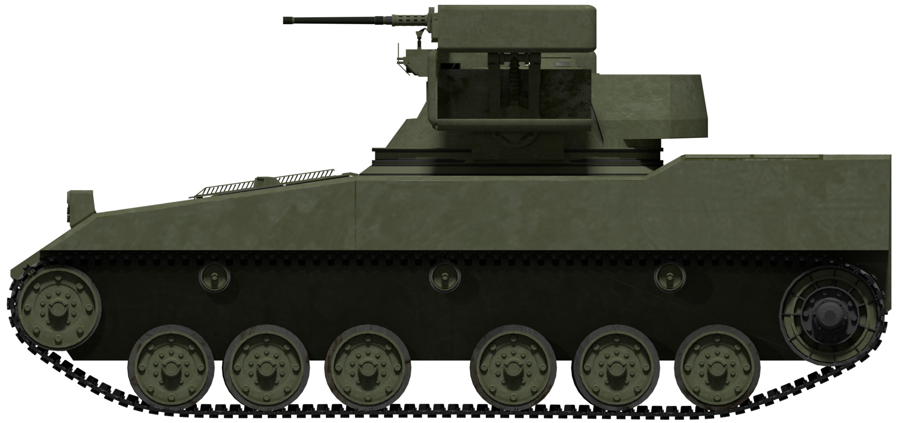
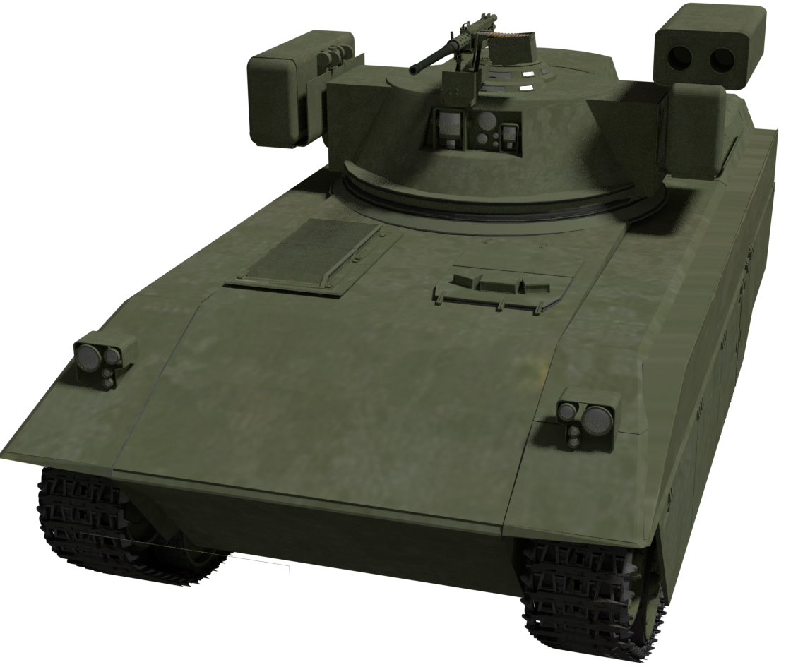
The baseline vehicle was a departure from the rather large body of the M2 Bradley. The essential layout, however, was very conventional. Riding on six wheels attached to what appear to be suspension arms, it appears to have torsion bar suspension, with the track running on these 6 sets of road wheels on each side which were divided into two groups of three and supported on the top with a trio of return rollers.
A driver sat in the front left with the power plant alongside on the right. Behind this was the fighting and troops’ space with a turret set slightly back from the center. The two-man turret carried all of the armament for the design, consisting of a single .50 caliber (12.7 mm) heavy machine gun with an elevation range of -15 to +30 and 1,000 rounds of ammunition. On each side of the turret was a pair of Dragon anti-tank guided missile (ATGM) launchers with another 4 missiles stowed at the back of the turret.
Finally, the troop space at the back, as can be imagined from a relatively small vehicle with a turret, was also small. Although only two men are shown drawn in the vehicle, it is probable that another two would be seated opposite for a troop space of 4 men, although how happy they would be to know that they were sat atop the 640-liter fuel tank is anybody’s guess.
It is important to remember though that the vehicle shown in the drawing, whilst more than a mere doodle of a viable armored personnel carrier (APC), should only be taken as an illustration of a possible future APC. The power plant work could just as legitimately be refitted to another vehicle as the key part of the study was not this APC per se, but a study to evaluate these power systems for AFV propulsion.

19.5-ton (17.7 tonne) Vehicle Concepts
With four (five including one minor amendment) configurations being considered, the design task was simplified by the specification of the engines to be used. The 19.5-ton (17.7 tonne) vehicle would use the Cummins VTA-903T generating 500 hp. The engine would then drive generator/s to provide power to various configurations of motors with a goal of a road speed of 45 mph (72.4 km/h).
Dimensions were set with a ‘datum’ concept vehicle with a hull height of 72” (1.83 m), an overall height of 96” (2.44 m), a distance of 150” (3.81 m) from the center of the front road wheel to the rear roadwheel, and a total length of 246” (6.25 m). The tracks were to be 17.5” (445 mm) wide with a total vehicle width of 110” (2.79 m). Armament was to be concentrated on a small turret located centrally width-wise and just back from the center of the length of the vehicle. All of the 19.5-ton (17.7 tonnes) vehicle concepts used an ‘engine forward’ arrangement leaving a large space in the rear of the vehicle suitable for carrying troops or other payloads. Armament was likewise the same on all of the 19.5-ton (17.7 tonnes) concepts: a single heavy machine in the small turret flanked on each side by a fire of anti-tank guided missile (ATGM) launchers.
Each design was identified by a concept number followed by a design number. For example ‘I-5’ was Configuration 1 Design 5, whereas II-5 was Configuration 2 Design 5 and so on. Vehicle concepts selected to go forward from theoretical design to a drawing stage were all allocated a drawing number starting AD-8432-xxxx.

Having outlined various conceptual vehicles, those which were successful were authorized to be drawn and, of those, five 19.5-ton (17.7 tonnes) vehicle concepts were selected on the basis of an efficiency scoring system that assessed a variety of factors such as weight, volume, the efficiency of the system, and technological ease. Despite it being a heavier system than the others, it was the Belgian ACEC system that was selected as being the best of all of the possibilities for the new vehicle. One proviso to this was that the Jarret system was received late in the assessment process and potentially could have been better than the ACEC – the design team recommended it receive further development too.


Production study
With the ACEC winning out, a production study was conducted as to problems and costs. The 192 hp DC motor in the design was not an issue, as it was already a well established piece of technology. It had already been used experimentally on a Belgian AFV called the ACEC Cobra several years before.
Although the ACEC system had already been used on the Cobra some years beforehand, there were significant differences. The study had selected the 500 hp Cummins VTA-903T whereas the Cobra used the 190 hp Cummins VT 190.
The 417 hp rare-earth metal permanent magnet (PM) generator (a Garrett design) used in the concept study was a problem. The generator required Samarium Cobalt (SmCo – a type of rare-earth magnet), and Inconel (a nickel alloy), an ingredients list which used strategic materials – specifically cobalt, a material which was difficult to work with in manufacturing, as it required special handling to prevent it from being damaged.
The result was that the cost of the drive-system without considering the final drives and cooling was estimated per vehicle at 1985US$19,500 (nearly US$47k in 2020 values) with a projection that the drives for the planned 400 vehicles would cost over 1985US$165,000 (just under US$396,000 in 2020 values).
Alternative Engines
Although the 500 hp Cummins VTA-903T was selected for the purposes of the study, it was accepted that other engines were available. In the end though, other than the possibility of switching to a petrol-turbine, the existing diesel engines were the only technology mature enough to be considered.

Of the 38 possibilities, three systems suitable for the 19.5-ton vehicle were identified. Concept I-5, from the Belgian firm of ACEC, came with the conventional DC (Direct Current) traction motor driven by a permanent magnet AC generator. The second was concept I-10 from the firm of Garrett which used its own AC permanent magnet drive, and finally, from the firm of Unique Mobility was concept IV-2 which used a dual-path AC permanent magnet drive system.
Other systems were considered as showing potential, even though they were not selected. These were the Jarret variable reluctance drive (using a single seed gearbox saving a lot of weight and volume with 84% efficiency) and the Westinghouse DC Homopolar drive (an extremely simple system albeit heavier than the equivalent mechanical system).
ACEC Drive System Detailed
The ACEC drive system consisted of a single 417 hp rare-earth self-excited metal permanent magnet (PM) generator (a Garrett design) operating at 18,000 r.p.m. This oil-cooled generator had an efficiency of 93.5% and a rating of 370 kVA. Connected to the 500 hp Cummins VTA-903T, it required a ratio transfer case operating at a ratio of 6.9:1 to raise the relatively slower rotating speed inside the engine to match that needed by the generator.
This sounded simple enough but the output from the generator was 3-Phase Alternating Current (AC) and had to be rectified into Direct Current for the ACEC motors. This was done using an oil-cooled 6 thyristor rectifier bridge allowing for bi-directional power flow and also for close control over the voltages. Operating at 747 Volts DC, this rectifier was 98% efficient.

The pair of ACEC DC traction motors were air-cooled and each rated at 192 hp, although they could deliver up to 300% of that capacity for up to 20 seconds. These were more than just drive motors too, as they also operated in the manner of generators when run with the field excitation voltage reversed, which allowed for steering and braking with the power generated fed back into the system and adding to the power of the generator. The motors were very compact too, just 2.35 cu.ft. (0.07 m3) each, with a diameter of 430 mm, length of just 460 mm, and a weight of just 700 lbs. (317.5 kg). Operating at 1,887 r.p.m. the motors could work at a maximum of 5,660 r.p.m. (for 20 seconds) operating at 420 Volts DC and with 93% efficiency over a 3 to 1-speed range.
These motors, on their own, were insufficient to provide all the power required to meet the desired road speed of 45 mph (72.4 km/h), so a two-speed 3:1 ratio oil-cooled gearbox was added with a constant mesh gear and clutch system of a type similar to that used in the X-1000 series transmission on the M1 Abrams.
The final element in the drivetrain was the 4:1 reduction ratio heavy-duty planetary drive coupled to the drive sprocket. For the ACEC-system vehicle, a maximum heat rejection of 3,677 BTU/Min (3,879 KJ/ Min) was needed.

Garrett Drive System Detailed
The Garrett system (I-10) consisted of a permanent magnet AC traction motor rated at 444 hp, also with a 2-speed gearbox and final drives. The AC generator itself was an oil-cooled unit of Garrett design using the rare-earth magnets to supply the field flux and operating at 747 Volts RMS at 18,000 r.p.m. with an efficiency of 93.5 %. As with the ACEC system, a ratio transfer case operating at a ratio of 6.9:1 was needed to raise the relatively slower rotating speed inside the 500 hp Cummins VTA-903T engine to match that needed by the generator.

The system from Garrett added an oil-cooled rectifier to provide feedback to the control system for the driver for the steering and braking of the vehicle. Operating at 747 Volts DC, this unit worked at 98% efficiency. This system was connected to a pair of 192 hp traction motors. Operating at 4,600 rpm, these oil-cooled motors, like the motors from ACEC, were capable of operating at up to 300% capacity and running at 18,500 rpm for up to 20 seconds.
The AC traction motors delivered speed across a 4 to 1-speed range but once more, like the ACEC system, was insufficient on its own to provide the necessary top speed desired. This system too was therefore also supplemented by an oil-cooled 2-speed gearbox, once more using a similar gear meshing and clutch system as used on the X-1000 series transmission of the M1 Abrams. Finally, the Garrett system used a 4:1 reduction ratio heavy-duty planetary gear driven by the output from the 2-speed gearbox to move the sprockets.
Cooling was an important factor in all of the system and calculations for the Garrett systems (both I-10 for the 19.5 ton and I-3 for the 40-ton) were calculated. For the 19.5 ton (17.7 tonnes) vehicle, a maximum heat rejection of 4,565 BTU/Min (4,816 KJ/ Min) was needed.
Unique Mobility Drive System Detailed
The drive system from Unique Mobility (UM) was different from the other systems in that it used two different paths for the delivery of automotive power, one mechanical and one electrical. The electrical system alone delivered power for speeds from 0 to 15 mph (24 km/h) and, when more power was needed to go above that, the mechanical system was unlocked and coupled to the electrical system. The control unit then controlled the power between these two units.
The electrical power was provided by a permanent magnet AC generator driven by the engine rectified to DC and then inverted in order to provide power to the traction motors. The generator was an oil-cooled Garrett-type rated at 400 hp and rotated at 18,000 rpm with 93.5% efficiency. The oil-cooled rectifier for this system operated at 685 Volts DC at 98% efficiency and connected to a 284 Volt AC inverter operating at 96% efficiency.
The traction motors used rare-earth metal magnets made from neodymium which removed the problem of the cobalt-type magnets, as the US had adequate stocks of neodymium. The cost of 400 of these power units was estimated to be 1985 US$145,000 (just under US$350,000 in 2020 values). The Garrett traction motors delivered 192 hp each and were able to operate at 200% for up to 30 seconds and deliver power to the final drive units which operated at a 4:1 reduction ratio.


Conclusion
Switching to an electrical transmission from a mechanical one could have provided several key benefits. It was more efficient, produced less heat through friction, and took up less than half the volume of the mechanical system. Half the volume meant more space available inside for fuel, weapons, and men, or just a smaller vehicle which therefore needed less armor and could be lighter.
With the transmission decoupled from the location of the engine and no drive shafts needed, the designers for the vehicle were free to make some radical layout changes if they wanted. This they did not do for this concept, as the layout remained rather ordinary. It is perhaps that which was the biggest failing of the study, as the vehicle shape and size were dictated from the start, meaning the single biggest freedom provided to the designers was gone. Instead, electric drive could only compete in terms of weight and volume and perhaps it was this ‘dictating the terms of the contest’ which was the main factor in why it was not adopted.
By working their way through the possible vehicle power options, the concept study team had made a clear choice. A relatively small diesel engine and the ACEC DC system were the most efficient and effective e-drive options for a new generation of vehicles in the 19.5-ton (17.7 tonnes) class.
Despite this, however, the idea was destined for obsolescence by the conventional diesel engine and mechanical powertrain on the M2 Bradley. The Belgians had made their ACEC motor-powered APC and even a light tank on the platform, but this American project fizzled out and more than 30 years later the idea of a diesel electric-powered APC has yet to be exploited to its full potential.
Specifications 19.5 ton (17.7 tonne) Concept |
|
| Dimensions (L-W-H) | 246” (6.25 m) overall, 92.52” (2.35 m) from front wheel to rear (centers) x 110” (2.79 m) x 72” (1.83 m) hull, 96” (2.44 m) overall |
| Tracks | 17.52” (0.45 m) wide, 150” (3.81 m) length ground contact |
| Total weight | 19.5 tons (17.7 tonnes) |
| Crew | ?? |
| Propulsion | 500 hp Cummins VTA-903T with electric drive |
| Speed | 5 mph (8 km/h) to 45 mph (72.4 km/h) |
| Armament | Single 0.50 calibre (12.7 mm) heavy machine gun with 1,000 rounds, pair of twin Dragon ATGM launchers with 4 spare missiles |
Sources
GDLS. (1987). Electric Drive Study Final Report – Contract DAAE07-84-C-RO16. US Army Tank Automotive Command Research, Development and Engineering Center, Michigan, USA
DiSante, P. Paschen, J. (2003). Hybrid Drive Partnerships Keep the Army on the Right Road. RDECOM Magazine June 2003
Khalil, G. (2011). TARDEC Hybrid Electric Technology Program. TARDEC
One reply on “19.5 ton Electric Drive Future Combat Vehicle (E.D.F.C.V.)”
This article and the one on the MBT we’re fascinating. I had no idea this technology was being applied to armored vehicles. Thanks for posting this and I hope you do more articles like them.