 United States of America (1918)
Ball Tank – None Built
The wheel is perhaps the second greatest of mankind’s accomplishments. Perfect, simple, and utilitarian, it takes an act of magnificent hubris to try and perfect such an already flawless instrument. However, not one to shirk a challenge, Arsene Pare, a magnetic healer from Canada living in Massachusetts, took up the challenge in 1917, creating what he hoped would be a weapon of war, but in fact was yet another failed idea of how to perfect a rolling vehicle to combat. Instead, he created yet another failed ball-type tank design.

Arsene ‘Andre’ J. Paré of Taunton
The man behind this ball tank was Arsene ‘Andre’ J. Paré of Taunton, Massachusetts, and he has one of the more unusual backgrounds for a tank designer. Arsene Paré, the son of Phillias and Ogelle Roy Paré, was a Canadian by birth, having been born in Quebec in 1876 (he was a US citizen by 1917). That means that, when he submitted his engine of war in 1917, he would have been around 41 years old.
He emigrated from Canada to the United States and by 1915 was living at 113 Wheeler Avenue, Brockton, Massachusetts, with his wife Goldie Pare (neé Dunbar) (b.1886, d.1964), whom he married in 1912. He worked as a masseur until progressing to the occupation of ‘magnetic healer’ by 1920, working in private practice. He would still be working in the role of ‘magnetic healing’ even through 1940, as recorded on the US Census that year.
It is unclear when Paré died, but his wife would later remarry and take the name Weinburg, passing away in 1964. With her, he had 3 children, two sons, Wynford (b.1914, d.1957) and Alfred (b.1919, d.1920), and one daughter who died at birth in 1915.
Purpose
Paré‘s stated intention was to produce a vehicle suitable for combat on both land and water and one which presumably had advantageous features over wheeled or tracked vehicles in either environment. Quite what the vehicle might have offered in terms of water passage can only have been for ease of travel, for the armament was so light, and the size so small, it would have been of no use as a combat vessel. On land, however, Paré was clear that its potential uses were that it “may be used for destroying hydrants, telegraph poles, poles for supporting trolley wires, railway cars, and small frame buildings by collision”.
Design
“A self propelled and armored engine of warfare”
The relationship between ‘magnetic healing’ as quack medicine and his design is unclear, but the vehicle design submitted by Paré at least has some science and rational thought behind it as a concept. Indeed, the general idea of a shell-type vehicle propelled from within has occurred several times for a military vehicle, but none proved successful. At the time of submission of his patent for this design on 1st May 1917, this was still a relatively novel concept.
Importantly, however, May 1917 was several months after the first use of tanks in September 1916 by the British in France, an action which gained considerable global attention and demonstrated the utility of a tracked vehicle over a wheeled one.
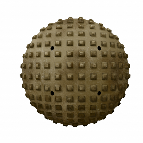
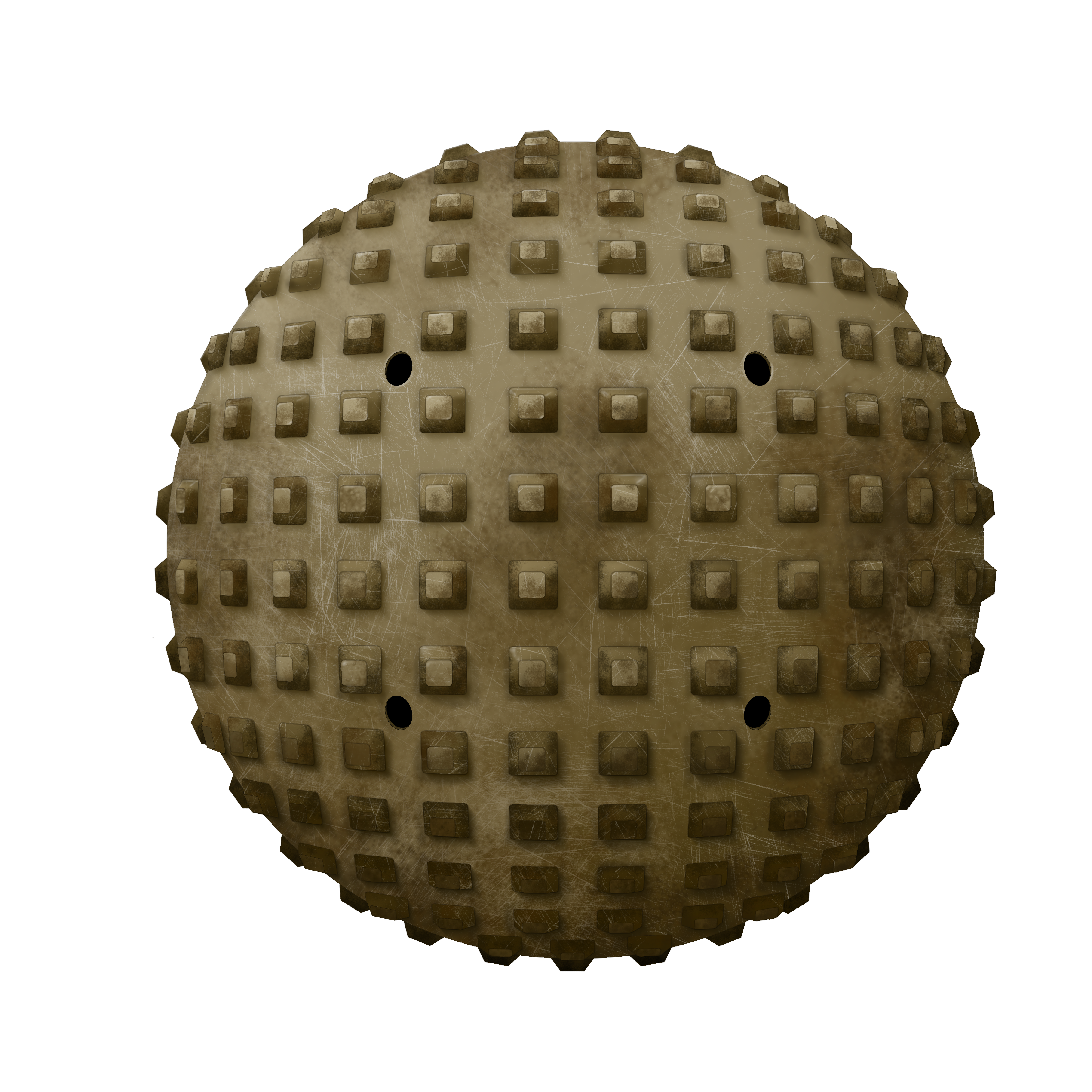
The form of the vehicle in the patent drawings only appears as a cross-section, but in real life, would have been spherical in shape. A pair of spheres in fact, with one rotating within the other. The outer spherical shell would be the protection and tractive part of the design, whilst the inner shell would house the crew and automotive components.
A driver’s position was located low down in the rear of the vehicle, directly behind the engine. On top of the engine and flanking the driver’s position was a horizontal platform just below the center line.
The outer shell, made from two hemispherical sections, had “knobs or protuberances” around the outside to press into the ground, providing grip. It was also pierced in multiple places coincident with the knobs, creating an open form of outer shell. These holes would allow water to enter the vehicle but, as the inner hull was watertight and so to were the drive shafts to the wheels, then the vehicle would also be able to operate on water as well as land. Those openings could be closed automatically when on the water as well for additional buoyancy but, when on land, should be open so that weapons could be fired from within the inner ball to an enemy outside through the small loopholes and also to provide ventilation.
The inner shell had 7 wheels which served to hold the inner shell off from the inside of the outer shell and provided the steering and propulsive action of the vehicle. One wheel ran within a recess at the top of the inner shell, another directly behind the driver, and another directly in front of the engine. Two more wheels, positioned between the engine and the driver’s controls, were arranged perpendicular to the sides on the inner shell. Together, all these wheels ensured the gap between the shells was maintained. The double-skin structure of inner and outer shells allowed them to rotate independently of each other and meant that the inner shell was inherently self-leveling, i.e. the inner shell would naturally remain vertical regardless of the orientation of the outer shell, although some rocking would certainly take place when the vehicle moved.
Internals
The engine was placed in the bottom of the inner shell, from which watertight shafts went to the front wheel of the inner shell to provide movement. Even if the external ports leaked, the mechanics would not be affected. The seat on which the single occupant would sit to operate the vehicle was directly behind the engine and fuel tank for the machine. This meant that not only was the weight of the engine below the center line of the vehicle but so was the driver.

Drive from the engine went forwards to a small gearbox and turned a pair of toothed gear wheels, each driving a chain that was connected to the primary drive wheel, being the wheel attached to the inner shell but running on the inside of the outer shell. The primary drive wheel was directly behind the driver, who would be able to control speed and braking by use of foot pedals. Steering for the vehicle was done by means of an awkwardly positioned handwheel descending from the roof of the inner shell towards the vehicle operator. Exhaust from the engine was vented backwards and to the left, being emitted into the gap between the two shells.

Source: US Patent US1265496.
Although no dimensions were provided within the patent for the size of the vehicle, the cross sections provide a good indication of how big it would be. In the image with the side view of the driver’s position, it can be estimated that an average man of about 170 cm might reach around a third of the way up the vehicle. This would mean a diameter of perhaps 6 m or so.
The platform on which the driver was seated was therefore large enough, as alluded to in the patent, to operate as a firing position for additional crew members who would fire weapons out of the small loopholes in the inner shell. The platform, being above the level at which the driver sat, would impede his view of where he may be going, so he would have to have relied on some instructions as to which way to go and how fast. The raised platform would, at least, enable soldiers within the vehicle to provide fire in an arc around the vehicle, although in such a confined space, on the move, and using something like a bolt action rifle, the firepower would not have been impressive.

Source: US Patent US1265496.
Steering
It was the large ‘top wheel’ and two smaller wheels perpendicular to the line of it, at the top of the vehicle, which were responsible for the steering of it. The two smaller wheels were also spring loaded – fitted into a cylinder so as a turning force was imparted on them they would connect to the inside wall of the outer shell and, once the steering force was removed, the spring would retract the wheel.
The action of these small wheels would be to shift the inner shell laterally within the outer shell. This would have the effect of moving the weight in that direction and cause a moving force upon the outer shell like a hamster in a ball.
Conclusion
The wheel is a perfect shape. The sphere is the ultimate shape of natural form and yet, despite trying to combine the simplicity of the wheel and the symmetry and prediction of the sphere, Paré achieved neither.
The design is perhaps unusual for combining some novel elements of engineering design, beyond those of the everyday man in the street, such as the steering system, but with incredibly naive military considerations. Not the least of those problems are expounded by the ideas of a simple platform from which to fight with basic weapons, like a rifle. No machine guns, no cannons, no proper gun mountings – just a rudimentary platform. The most useful part of the concept might have been the use of it for ramming items of infrastructure to destroy them, like telegraph poles, as this would have required the least skill by the operator to perform. It would, however, have caused grievous risk to the soldiers standing on that platform trying to fire outwards.
The utter lack of visibility for the driver was also a problem, not to mention any practicalities of this machine actually getting to the battle in the first palace without crushing its own infrastructure or its knobbly protrusions tearing up the roads on the way. Too many questions are left not only unanswered but also seemingly not even considered at all. These would indicate a project which might have been designed with good, honest, and noble intentions to create a weapon to fight the war in Europe. However, what was produced was very naive and illustrated the designer’s lack of knowledge of how the war was being fought with the new ‘tanks’ the British were using. Quite what Paré thought his design might genuinely offer over other vehicles is unclear and the design went nowhere.
Specifications Paré’s Engine of War |
|
|---|---|
| Crew | >2, driver plus soldier to operate weapons. |
| Dimensions | ~spherical approx. 6 m diameter |
| Engine | unknown |
| Speed | unknown |
| Armour | unknown |
| Armament | Soldier’s personal weapons fired from within |
Sources
https://www.findagrave.com/memorial/119769172/wynford-arsene-pare
https://www.findagrave.com/memorial/119767628/alfred-dunbar-pare
Manifests of Passengers arriving at St. Albans Vermont, District through Canadian Pacific and Atlantic Ports 1895-1954.
Massachusetts Marriages 1841-1915, Sheet 176, Page 18.
US Census 1930 S.D. 14, E.D. 18-29, Sheet 14B.
US Census 1940 S.D. 15, E.D. 12-38, Sheet 1A.
US Patent US904146, Steering mechanism for motor vehicles, filed 2nd April 1908, granted 17th November 1908.
US Patent US1265496, Engine of Warfare, filed 1st May 1917, granted 7th May 1918.
3 replies on “Paré’s Engine of War”
Ah yes, the rolling ball of death!
How were the soldiers supposed to enter and leave the contraption? On the first drawing there is some structure in the upper left sector (68, 69, 71) that could be a hatch. But how would one align a hatch in the outer ball with a corresponding opening in the inner ball?
exactly what I was thinking. it would bee very difficult at best to align the hatches to escape even when it was operating, let alone if it was disabled and on fire. also not clear how the driver could see where he was going. even if you made holes in the outer shell, the view would be fleeting and they would quickly be filled up with mud and debris. absolutely insane concept, in the most literal sense.