 Federative Republic of Brazil (1977)
Armored Vehicle Launched Bridge – None Built
In 1976, Brazil built its first bridgelayer, known as the XLP-10. The XLP-10 was based on a modernized Stuart hull, also known as an X1 hull, and carried a 10 m long bridge which could support up to 20 tonnes. Realizing that the capacity of this bridge was fairly limited as it would not be able to support the 83 M4 Shermans nor the 353 M41 Walker Bulldogs of the Brazilian tank fleet, the team behind the XLP-10 designed a bridge-layer based on the M4 Sherman chassis.
Due to the relatively limited number of Shermans in the country, none of the Sherman modernization attempts turned out to be a success. Brazil had figured that modernizing their 437 M3s was much less risky. and, by the time they had time to modernize a new vehicle, they had enough experience to modernize the M41, leaving the M4 to never receive any modernization. Although a few Shermans were converted into other prototypes, the XLP-20 never left the drawing board.

Bridging the First Gaps
The bridge-laying projects of the Brazilian Army seem to have started somewhere in between September 7th 1973 and September 29th 1974, with the first mock-up of a Stuart-based bridge-laying vehicle appearing on the later date. At the time, Brazil had initiated the X1 program to modernize its Stuarts to get more use out of them and to gain experience in modifying and building tanks. These programs were initially carried out with the companies Bernardini and Biselli, but Biselli stepped out of the defense industry around the mid-1970s.

Source: Blindados no Brasil
The XLP-10 program started off with an electric bridge-laying design by the Instituto Militar de Engenharia (IME, Institute of Military Engineering), but at some point, the Instituto de Pesquisas e Desenvolvimento, (IPD, Research and Development Institute) authorized the Parque Regional de Motomecanização da 2a Região Militar (PqRMM/2, Regional Motomecanization Park of the 2nd Military Region) to develop its own bridge-laying design.
The PqRMM/2 was essentially the center where all the re-engining, modernisations, and new designs were developed and carried out. The PqRMM/2 was, for example, responsible for the re-engining of the M8 Greyhounds with diesel engines, the X1 tank program, and the development of what would become the EE-9 Cascavel. The PqRMM/2 came forward with a hydraulic bridge laying design and wrote up a report comparing it to the IMEs electric design.
Among the critiques were that the electric design from the IME was incapable of fully automatic bridge-laying, as the crew had to get out of the tank to manually couple or decouple the cables from the bridge. The design had an excessive height and the telescopic bridge-laying system was not functional, as it could not get low enough to lay the bridge over shallow river beds. The report was passed on to the Diretoria de Pesquisa e Ensino Técnico (DPET, Army Research and Technical Educational Board), which was the overarching military institution of the IME and the IPD, which decided to go for the hydraulic design to concentrate all the efforts into a single project.
The PqRMM/2 team and Bernardini delivered the first XLP-10 which was presented on the independence day parade of September 7th 1976. From there, 4 more XLP-10s were manufactured, which would all enter service in the early 1980s. It is thought that, after the success of the XLP-10 prototype in 1976, that the PqRMM/2 team started designing a similar bridge layer on a modernized M4 Sherman platform.

The Brazilian M4 Shermans
Brazil received 53 M4 Shermans through Lend-Lease during the Second World War. This is quite remarkable, as Brazil was the only South American country to receive Shermans through Lend-Lease, giving an idea to Brazil’s importance on the continent. This number would grow to a total of 83 Shermans after the country received an additional 30 Shermans through the Military Assistance Program (MAP). These Shermans consisted of standard M4s, early M4 composites, late M4 composites, and M4A1s. The main differences between the two composite types, known as CH-1 and CH-2 in Brazil, were the two hatch turret and the redesigned commander’s cupola for the late version, among other things.

By the late 1960s, many Brazilian vehicles required overhauling or modernisation, as the vehicles were over 25 years old. The M3 Stuart, in particular, received an extensive overhaul program known as Plano Impere (Empire Plan or Plan Empire). Brazil had a methodical approach to modernizing its vehicles. The PqRMM/2 team would begin with replacing the original engine with a locally produced and fully national diesel engine. This meant that Brazil attempted to fully transition its army to diesel fuel, although this would take until the 1990s to be carried out fully.
Among these initial re-engining projects was, of course, the M4 Sherman. Plans were drawn up as early as 1969 and the team opted for the MWM TD 232 V12 diesel engine. This engine could produce 406 hp, and on request from the PqRMM/2 (specifically the Centro de Pesquisa e Desenvolvimento de Blindados, CPDB, Center for the Research and Development of Tanks branch of the PqRMM/2 team), an aftercooler was installed which further increased the engines power to 500 hp. This would theoretically change the MWM TD 232 V12 into a MWM TBD 232 V12 engine instead, as the B specifically referred to a charge cooler or aftercooler for the turbocharger (D= standard diesel engine, TD Turbocharged, TBD Turbocharged and charge cooled).
Due to the limited number of M4 Shermans and them being overall more valuable than the M3 Stuart, the Sherman modernization was delayed in favor of modernizing the M3s. It would take until 1974 for the PqRMM/2 team to start replacing the engine and the project was completed and tested in 1975. After the tests were satisfactory, the company Biselli would switch out the older Vertical Volute Spring Suspension (VVSS) suspension with the newer Horizontal Volute Spring Suspension (HVSS, also known as the ‘E8’ suspension) from one of the three M74 recovery vehicles of the Brazilian Army. After this rebuild, the project was again put on hold in favor of the Stuart based projects.

The XLP-20’s Foundations
The M4 Sherman modernization was returned in 1977 in the form of a bridge-laying vehicle known as the XLP-20. The X stood for prototype, LP for Lançador de Ponte (Bridge Layer, literally Bridge Launcher), and the 20 for the length of its bridge, which was to be 20 m. The vehicle was to be designed by the IPD and Bernardini, with Bernardini acting as the manufacturer as well. The materials of the bridge were to be provided by the Brazilian subsidiary of the Canadian aluminum company Alcan. Supposedly, they also helped with the design of the bridge. It is possible that, due to the initial lack of knowledge in working with aluminum, Alcan would have also acted as the manufacturer of the bridges if the program went into production.
When exactly the design was initiated is unknown, but it might have been soon after the trials of the XLP-10 were completed and the 4 production vehicles were ordered, somewhere likely around late 1976 to some point in 1977.
The XLP-20 is in essence an upscaled and further developed XLP-10. It would make sense for the Brazilian Army to only initiate its development if the overall concept of the cantilever bridge laying method of the XLP-10 worked and met Army requirements. The XLP-20 was supposed to use a modernized Sherman chassis which could suggest that it would use the MWM V12 engine.
Interestingly, the design sketches show a VVSS suspension instead of a HVSS which was mounted on the latest iteration of the modernized Sherman. Supposedly, the Brazilians never made a copy of the HVSS suspension and would have to rely on importing them. Why Brazil never copied the HVSS suspension is unknown. Considering they copied the M3 Stuart, M4 Tractor, parts of the M4 suspension, and the M41 suspension, it would likely not have been beyond the capabilities of the Brazilian engineers.

The XLP-20 in Detail
The writer would want to put a disclaimer for the technical description of the XLP-20. Considering the design never left the drawing board, many specifications are simply unknown. The writer will attempt to work with the specifications which are either given, suggested or measured, but please note that these are estimations on what the XLP-20 would have looked like and functioned from a technical point of view.
The Sherman presented in the sketch is either an M4 or M4A1 Sherman. Considering Brazil had 36 M4 Shermans and only 2 M4A1s, the description will use the technical details of the M4 Sherman. The single biggest issue is represented by the dimensions of the bridge itself based on the technical drawing. When compared to the M4 or M4A1 Sherman, the lengths simply do not line up. The bridge’s potential lengths will be more thoroughly analysed in the bridge sub-section further on.
The M4 Sherman weighed about 30.3 tonnes in total, of which the turret itself weighed around 4.5 tonnes. Considering the turret would be removed and replaced with a bridge weighing around 8 to 9 tonnes, the XLP-20 would have weighed somewhere in the region of 35 tonnes. A campaign manual from the Brazilian Army lists an estimation of 34 tonnes.
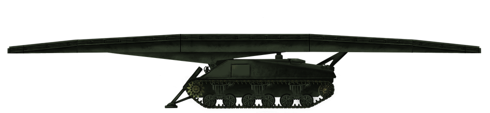
The hull would be an estimated 5.89 m (19.3 feet) long, 2.62 m (8.6 feet) wide, and an unknown height. The height is difficult to determine due to the cantilever frame being hidden behind the bridge in the drawing. If a similar design style is considered as with the XLP-10, the cantilever frame would reach to about halfway the height of the bridge, giving a height of 2.5 m (8.2 feet) without bridge. The XLP-20 was about 18.5 to 20 m (60.7 to 65.6 feet) long, 3.5 m (11.5 feet) wide, and 2.9 m (9.5 feet) tall with the bridge. It would have likely had a two man crew, like the XLP-10, consisting of a driver, who could lay the bridge from his station, and the co-driver, who would assist the driver with laying or retrieving the bridge outside the vehicle if possible.
Hull and Armor
The hull would have essentially been that of a modernized Sherman. Considering only the engine changed, the armor protection should have been the same as on the M4 Sherman. The upper front and lower front plates would have been 51 mm (2 inch) thick. The sides and rear were 38 mm (1.5 inch), the top 19 mm (0.75 inch), and the floor 25 to 13 mm (1 to 0.5 inch).
If the XLP-20 would have had its hull machine gun removed like the XLP-10 is unknown. Considering this was done for the XLP-10 to facilitate a two hatch system for ease of leaving the vehicle for the co-driver and this style of hatch design would not have been possible on the M4 Sherman, it is a possibility that it would have retained the hull mounted .30 Cal (7.62 mm) Browning M1919 machine gun.
Like the XLP-10, the hull would have had two hydraulically powered pistons fixed on a pivot on the front which extended an outrigger to prevent the Sherman from tumbling over when laying the bridge. The foot of the outrigger would be connected to a rotating bar which would ensure that the foot would face the ground at full stroke. The interior of the vehicle would have housed certain components to enable laying the bridge, such as switches and the components for hydraulics. These could have included a hydraulics tank, a pump and the pistons for the cantilever system.
Mobility
The engine of the XLP-20 is unknown. Considering the re-engining of the Sherman a few years before the XLP-20 program, it is quite likely that, had those modernisations gone through for the Sherman fleet, the XLP-20 would have used the same engine. The main reason for this would be for logistical reasons in both components and usage of diesel fuel. The XLP-20 would thus have most likely had a turbocharged MWM TBD 232 V12 diesel engine with a likely power output of 500 hp. This would have given the XLP-20 a potential 14.3 hp/ton ratio compared to 16.5 hp/ton for a potentially modernized M4 Sherman. It would have used the same but possibly revised transmission as the original Sherman, with 5 gears forward and 1 in reverse. The top speed and range are unknown, but due to the increased mass of the tank, would have likely been less than the 34 km/h and the 160 to 192 km (100 to 120 miles) operational range of the standard M4 Shermans.

The XLP-20 would have used a VVSS suspension according to the design sketch. It would have had 6 road wheels divided over 3 bogies per track. Each bogie would also provide a single return roller on top, and the vehicle would have the drive sprocket at the front and the idler on the rear. The XLP-20 would have had an on ground track length of 384 cm (12.6 feet) and a track width of 42 cm (16.5 inches), giving the vehicle an estimated ground pressure of about 1.09 kg/cm2 (15.5 lbs/in2).
The Bridge
The dimensions of the bridge are debatable for a number of reasons. According to Expedito Carlos Stephani Bastos, the bridge was 20 m (65.6 feet) long, while according to Paulo Bastos, the bridge was 18.5 m (60.7 feet) long. The only sketch currently available does not provide any form of measurement and thus seems mainly to show how the concept would more or less have looked like with its main features. When using the M4 Sherman from the sketch as a basis, the bridge would be about 18.8 m (61.7 feet) long by using ratios to calculate the bridge length.

This seems to suggest that the claim from Paulo Bastos is more reliable, but keep in mind that the name of the vehicle is XLP-20 and the design sketch does not seem to have been focussed on specific dimensions. The possible dimensions of the bridge are displayed in the table below for each potential bridge length.
| Bridge length | 18.5 m (60.7 feet) | 18.8 m (61.7 feet) | 20 m (65.6 feet) |
|---|---|---|---|
| External width | 3.5 m (11.5 feet) | 3.5 m (11.5 feet) | 3.75 m (12.3 feet) |
| Internal width | 0.7 m (2.3 feet) | 0.7 m (2.3 feet) | 0.75 m (2.5 feet) |
| Lane width | 1.4 m (4.6 feet) | 1.4 m (4.6 feet) | 1.5 m (4.9 feet) |
| Folding end length | 2.75 m (9 feet) | 2.8 m (9.2 feet) | 3 m (9.8 feet) |
| Height | 0.7 m (2.3 feet) | 0.7 m (2.3 feet) | 0.75 m (2.5 feet) |
The bridge would have been made from aluminum and would have weighed around 9 tonnes. In contrast to the XLP-10, which had an internal width of 1.36 m, the XLP-20 would have likely not needed additional lanes to allow jeeps to cross the bridge, as the internal width of the XLP-20 would have been around 0.7 to 0.75 m. A requirement of the XLP-10 was that it could lay a bridge 0.3 m (1 foot) below ground level, which would likely have been maintained for the XLP-20. The bridge was to be laid and retracted in 5 minutes and was to carry vehicles of around 30 tonnes.
In essence, the bridge structure would have consisted of three main structures. The inner supporting structure and cantilever, which is known as the main frame, on which the bridge rested, would retract back and forth, and laid the bridge on the ground.
The second structure was the bridge itself. The bridge would have rested on top of wheels which were attached to the cantilever structure of the XLP-20. A C-shaped beam with a roller track was attached to both inner sides of the lanes. These tracks were driven by a hydraulic motor which drove the bridge forward and backwards through a sprocket.

The third structure were the folding ends. The folding end style bridge-layer seems to have been mainly inspired from the Soviet MTU-20 and MTU-72, which also use a cantilever and folding end system. The MTU bridge-layer folding ends function by having a bar connected to the foldable end, which is then connected to a hydraulic piston within the main bridge section. To fold open the bridge, the piston retracts and thus folds the bridge open by pulling the connecting rod inward. After the bridge is folded out, it is ready to be laid.
It is not completely certain how the system allows for ease of use for the hydraulic system inside the bridge itself for the foldable ends. It is thought that the bridge itself had quick-release connectors which would enable the bridge to be released from the hydraulic system without losing pressure in the hydraulic system of the bridge. It is also possible that the bridge was purely held in place by the folding sections locking into place, which would be unlocked when the bridge was retracted on the vehicle again through hydraulics, or it is a bit of both systems.
Since the bridge uses the exact same path for both laying and retraction, it would be possible to make the quick connectors at a fixed position so that the bridge can also fold in the ends when it is picked up again. The writer thinks that this concept would have likely been used on the XLP-20 as well if it was built.

The Hydraulics
The hydraulic system would essentially have powered 4 main components, which were the hydraulic motors for the bridge, the pistons of the cantilever, pistons for the folding ends, and the pistons of the outrigger, which prevented the XLP-20 from falling over. If the design concept of the XLP-10 was used for the XLP-20, then the hydraulic pump would be connected to the engine through gears and controlled from the inside by three levers. To protect the system, a solenoid valve with an electric sensor would have been added to prevent the activation of commands in the wrong order. The flow and pressure were regulated with valves and the hydraulic fluid was stored in a reservoir.
How the Bridge Got Laid
The process of laying the bridge would have essentially been exactly the same as for the XLP-10, but with an additional step, totalling 5. The XLP-20 would drive up to the gap and let the pistons of the outriggers fully extend in order to keep the vehicle in place. The folding ends would then be extended by the hydraulic pistons in the bridge frame. Then the bridge would be fully extended through the hydraulic engines. The cantilever pistons would then push the cantilever upwards and thus cause the bridge to be laid on the ground. Finally, the bridge was decoupled. The bridge would be picked up with the above mentioned process but reversed. This process would take about 5 minutes.

Fate and Conclusion
In the end, the XLP-20 never left the drawing board. It might have boiled down to simply being more worthwhile to invest in the M3 and the M41 modernisations instead because of the limited numbers of Shermans available. A number of attempts to modernize the M4 and other engineering concepts were attempted in the 1980s, but these failed to see success as well.
While converting most or perhaps even all of the Shermans into engineering vehicles could have been a fairly useful way to keep them in service, it would also mean that spare parts and logistics would have to be maintained for a vehicle type the Brazilian Army wanted to retire. Although it would take until 1988 for Brazil to officially retire the M3 Stuart and M4 Sherman, the process to stop using front transmission driven vehicles already started in the early to mid 1980s.
While the XLP-20 was not necessarily a bad idea to support regiments and brigades which had vehicles too heavy for the XLP-10, the number of M4 Shermans available in Brazil seems to have been the main limiting factor. It was simply more worthwhile to invest time and energy in M3 Stuarts and M41 Walker Bulldogs, which were available in large quantities. While it would not be the last attempt to find use for the old M4 Sherman, modernizing and then converting Shermans may have simply been more trouble than it was worth.

Illustration of the XLP-20 AVLB produced by Rolan Reboso, funded by our Patreon Campaign.
Specifications |
|
| Dimensions (L-W-H) | L: 20 – 18.5 m (65.6 – 60.6 ft) long w/ bridge, 5.89 m (19.3 ft) w/o W: 3.5 – 3.75 m (11.5 – 12.3 ft) overall, 2.62 m (8.6 ft) hull only H: Est. 2.9 m (9.5 ft) w/ bridge, 2.5 m (8.2 ft) w/o |
| Total weight | 34-35 tonnes (37.5-38.6 US tons) w/ bridge, 25 tonnes (27.6 US tons) w/o |
| Crew | 2 (driver & co-driver) |
| Propulsion | MWM TBD 232 V12 500 hp |
| Speed (road) | <34 km/h (<21 mph) |
| Armor | Front: 51 mm (2 in) Sides: 38 mm (1.5 in) Rear: 38 mm (1.5 in) Top: 19 mm (0.75 in) Floor: 25 to 13 mm (1 to 0.5 in) |
Sources
Special thanks to Expedito Carlos Stephani Bastos, the leading expert of Brazilian armored vehicles (ecsbdefesa.com.br), Jose Antonio Valls, an Ex-Engesa employee and expert in Engesa vehicles, Paulo Bastos, another leading expert of Brazilian Armored vehicles and the author of the book on Brazilian Stuarts and the website (tecnodefesa.com.br), Adriano Santiago Garcia, a Captain in the Brazilian Army and ex-company commander on the Leopard 1 and ex-lecturer on the Brazilian Armored School, and Guilherme Travassus Silva, a Brazilian with whom I was able to endlessly discuss Brazilian Vehicles and who was always willing to listen to my near endless ability to talk about them.
Brazilian Stuart – M3, M3A1, X1, X1A2 and their Derivatives – Hélio Higuchi, Paulo Roberto Bastos Jr., Reginaldo Bacchi
Blindados no Brasil – Expedito Carlos Stephani Bastos
Lançador de Ponte XLP-10 – Expedito Carlos Stephani Bastos
Lançador de Ponte XLP-20 – Expedito Carlos Stephani Bastos
Jane’s Light Tanks and Armoured Cars of 1984
Worldwide Tank Fire-Control Systems – CIA
www.lexicarbrasil.com.br
Personal correspondence with Expedito Carlos Stephani Bastos
Personal correspondence with Paulo Roberto Bastos Jr.
Caiafa Master
Engesa brochures and manuals
Cockerill brochures
TM 9-785 18-Ton High Speed Tractors M4, M4A1, M4C, and M4A1C – US Army April 1952.
Stuart: A history of the American Light Tank, Volume 1 – R.P. Hunnicutt
Tecnologia Militar Brasileira magazine