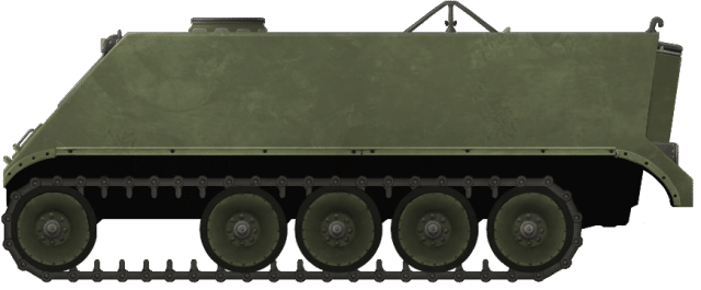
 United States of America (1966-1995)
Armored Personnel Carrier – 1 Prototype Built
The potential of electric drive for the M113 Armored Personnel Carrier (APC) was examined in 1966 by the vehicle’s parent company, the Food Machinery Corporation (FMC). This took the shape of a standard M113A1 driven by means of two high-speed AC induction motors built for FMC by Garret AiResearch (later Allied-Signal Air Research) in 1966. An electric transmission could have significant benefits for the platform enabling, for example, improved performance and a reduced maintenance burden.
The drive system consisted of a stator assembly inside a housing and a rotor assembly on a shaft. These two stator housings attached at each end to a common housing on the non-drive end and planetary gearbox on the drive-end respectively. Drive from the gearboxes then went via a second reduction set of gears to the final drives powering the sprockets to drive the vehicle.
Mechanical disc brakes provided the braking for the drives and the motors, as is common with electric drive systems, were cooled by oil.
Since its inception, this vehicle was only ever a test bed for the technology and as such, was frequently modified and upgraded. Several different engines were tested from gasoline, to diesel rotary, and even a turbine type with on-board electrical power provided by batteries. The original controls, which were a thyristor-based system, had, by 1994, been changed to a bipolar junction transistor (BJT) based system instead. The vehicle had actually been serving with the Sacramento Municipal Utility District (SMUD) for a while too until the early 1990’s, when new ideas about hybrid-drive technology started to be examined seriously by the military.
1984 Quietness Work
In 1984, the M113 EDTB found itself used for trials into noise reduction. New low-noise road arms and wheels for the vehicle would be manufactured. The new road arms would consist of a pair of rubber isolators placed between the hull body side and the road arm and between the steel tube surrounding the torsion bar, to absorb vibration. The rubber isolators proved very successful and reduced road noise by 22dB at a frequency of 250 Hz.

M113 EDTB seen in ‘roadwheel-only’ test configuration to measure road noise. Photo: Schmiedeberg et al.

Details of the experimental quiet roadwheel mount. Photo: Schmiedeberg et al.
1985 Track Use
In 1985, work on rubber tracks was undertaken by David W. Taylor Naval Ship Research and Development Center as part of their work on a corrosion-resistant track for use in a marine environment. For the purposes of that test, the M113 was simply being used as a surrogate for the 14-ton Automotive Test Rig (ATR) developed by AAI.

M113EDTB seen in 1985 testing the AAI band track. Photo: AAI Corp
The M113 EDTB was sent to AAI for installation of the band-track and from there, shipped to Camp Pendleton for a 500 mile (805 km) test over a 26.7 hour period. After this, the track was removed and returned to AAI for inspection.

Close-up on the band track installed on the M113EDTB in 1985. Photo: AAI Corp
A New Life for the ’90s
Sent to SMUD, which was interested in electric vehicle technology to reduce air pollution, the vehicle was brought back to FMC for upgrading in 1994 as part of the M113 Vehicle Refurbishment Project (VRP). The VRP was, itself, part of the Advanced Research Projects Agency (ARPA) Electric and Electric Hybrid Vehicle Technology program (EEHVTP) program which had been established in 1993.
The goal of the M113 VRP was to bring the existing FMC-owned M113 vehicles equipped with mechanical drives up to date, which was to be done by installing two large battery packs and an improved power converter and motor controller assembly.
As a result, the single existing FMC-owned M113 Electric Drive Test Bed (EDTB), which had been converted to electric drive in 1966, was to be brought back and updated as a demonstrator vehicle for the government and industry to examine. However, due to lack of funding, the upgrading and demonstration of the M113 EDTB, which was planned in October 1993, could not start until the contract award was made in February 1994.
The contract for work was for just 2 years (end-date 16th February 1996) and would update the drive and improve reliability with an overhaul of the vehicle too, bringing it up to current military standards. Initial testing was to begin in May 1994 in Atlanta followed by the fitting of a new battery pack consisting of the GNB lead-acid batteries purchased by ARPA. These were then modified to increase system voltage and high-speed performance and the vehicle tested in Smuggler’s Notch, Vermont, in September 1994.
Between those two tests, new motor controllers had to be designed, built, and fitted. The old 6-step DC link current regulated, slip controller system was replaced with the most up-to-date power converter available, an Insulated Gate Bipolar Transistor (IGBT) type inverter which was faster and more reliable than the old system. The conversion which was finished and installed by April 1994. The new battery packs were installed in March and April 1994 and the vehicle was ready for its initial testing ahead of schedule.
The newly modified M113 was described thusly:
“An M113 vehicle with a modified propulsion system comprised of a dual-motor sprocket driver assembly, a power converter assembly, a [sic: an] auxiliary power unit (APU), battery packs, an energy dissipater, vehicle cooling system, power distribution, and cabling, and energy management and vehicle controller.”
– FMC
The APU was a 500hp auxiliary unit with an electrically driven cooling fan producing 3-phase AC power which was then converted to DC power for the traction and fan inverters.
At the time of refurbishment, the vehicle was being powered by a 560 ci (9.18 litre) V9 engine delivering 375hp regulated by an electronic limiter on the vehicle reducing its maximum speed to 4000 revolutions per minute (rpm), increasing the working life of the unit. Unlimited, the engine was capable of delivering 500hp although this reduced engine life.

Power converter inside the engine bay of the M113 EDTB. Photo: FMC
The generator was a Westinghouse 3 phase unit delivering 312 kVA connected to the engine by means of a quill shaft. The new GNB MSB series high-density lead-acid battery pack was to consist of a total of 90 batteries installed in two sections; 60 and 30 respectively. These 60 batteries (divided into two rows of 30) were to form a 240VDC pack in conjunction with the monitoring and charging system, whilst the remaining 30 batteries were integrated into the power system for a vehicle.
The first 60 batteries were further divided into groups of 4 and arranged in 5 vertical columns on the left-hand sponson of the vehicle enclosed in an aluminum ventilated box. Connected together in two sets of 30, they formed a single pack delivering 240 volts/207 amp/hours to the power converter.
The second set of batteries, 30 of them, were installed into the floor of the vehicle located between the first battery pack on the left and the PAU on the right and were grouped together in fours. Altogether, these 90 batteries formed 3 parallel lines of 30 batteries each for a total of 260 volts / 207amp/hours of power to the power converter

Rear view of the FMC M113 EDTB with the upgraded battery packs and new APU fitted. Photo: FMC

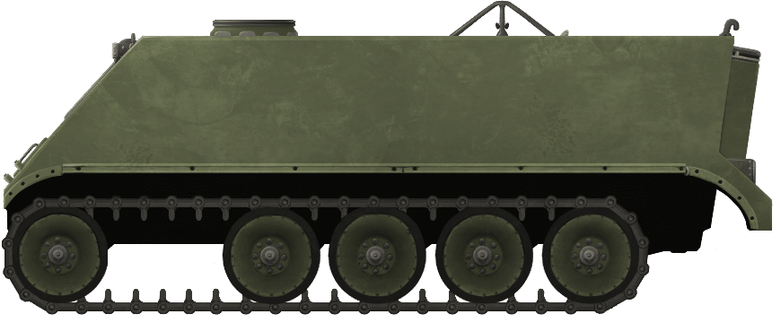
FMC’s M113 Electric Drive Test Bed (EDTB) in the ‘roadwheel-only’ test configuration to measure road noise.

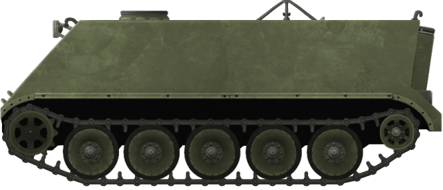
M113 EDTB with the standard suspension layout, testing the AAI band tracks.
Both Illustrations were produced by Andrei ‘Octo10’ Kirushkin, funded by our Patreon Campaign.
Further Modifications
The controls for the vehicle were converted to more closely match those of the Bradley Infantry Fighting Vehicle (BIFV). The gunner’s control handle, for instance, was turned into the steering control and a new brake pedal had been added.

Driver’s station on the M113 EDTB showing the new steering controls and instrumentation. Photo: FMC
The vehicle also required a new cooling system as these electrical components got hot during use. This system consisted of a 16” (406 mm) electrically-driven 10hp fan made by Dynamic Air with 3 heat exchangers and three separate cooling circuits. The first, a low-temperature type system, was just for the power converter assembly, whereas the second circuit was a high-temperature system which used oil to cool the auxiliary power unit. The third cooling system again used oil and was there simply to cool to drive motors. Two electrically-driven pumps provided the circulation of the coolant through the drive motors and power converters and were located under the floor along with the batteries.
Suspension
Despite the weight of the additional equipment, no work was done on the suspension to improve the load carrying capacity, but it was spaced 1” (25.4 mm) further away from the hull in order to accommodate a new, wider track. The track, however, was changed. The existing 15” (381 mm) wide single-pin steel track was too noisy and too heavy, and was switched out for the experimental AAI Band Track developed by ARPA/TACOM. This new, 17” (432 mm) wide rubber track was lighter – just 35lb (15.9 kg) per foot compared to 42lbs (19.1 kg) per foot for the steel type – and more efficient with lower ground resistance than the old steel, plus reduced vibration to the vehicle too. This then was the second time this vehicle had been tried with this track.
Performance
Tests on this new M113EDTB were carried out to examine and compare performance both with and without assistance to the drive from the batteries and APU. The batteries and APU were found, in particular, to improve the slope climbing performance of the M113 by between 25% and 200%, as well as, a significant improvement in acceleration. Instead of taking nearly 1 minute to reach top speed compared to when using the hybrid drive to its fullest, it theoretically could reach 40mph (64.4 km/h) in just under 10 seconds. The problem was that because of the way that the controls had been configured, the drive could only use power from the APU or the batteries, but not together. The vehicle needed to use both together to be a true hybrid, but the sub-10 seconds 40mph time was not far from the speed from the APU on its own.
As a point of note, when driven solely on batteries, the vehicle could still manage 30mph, although it took nearly a minute to reach this speed. Demonstrations and trials had started in May 1994 and continued through July 1995 with multiple demonstrations to ARPA and TACOM.
Further Recommendations
Following the tests in 1995, there were some further refinements suggested to the M113EDTB. Firstly, the existing STH nickel-cadmium batteries made by SAFT, and the GNB MSB series high-density lead-acid batteries should be replaced with 54 Horizon Advanced lead-acid batteries made by Electrosource, which had a better energy density and a lower profile. Better use of space should also be made with them so they take up less space inside the vehicle, part of which would be achieved with these batteries, as 6 of them could be mounted under the seat on each side. The remaining 42 would be located in the left and right sponsons. The controls should be modified too to ensure that they were reflective of a true hybrid vehicle and additional test equipment installed.

Suggested new hybrid drive arrangement post 1995. Photo: FMC
Finally, the AAI band track, an improvement over the original steel track was, itself, to be replaced with the new Quimpax band track which was quieter and more reliable and had been first made in 1984, but had only been trialed for 700 miles in the intervening decade.
In 1994 a separate contract from TARDEC, Quimpax were to begin manufacturing its endless belt rubber track starting in October to test on the M113. Prior to this, it was tested by TARDEC on an unspecified British APC and found to work well so it was expected to provide good performance for the M113 too. Experiments for it on the Bradley IFV were expected to follow at some point.
Conclusions
The M113EDTB was built in 1966 to show off a high-frequency induction AC type electric drive system. Since that time it received numerous modifications and changes. The most significant change took place in 1994 with the addition of a semi-hybrid drive which was followed by a recommendation for a full hybrid drive to be fitted. The potential of electrically driven vehicles was not capitalized on in 1966, and, despite encouraging signs, such as significant improvements in acceleration and mobility, the work in 1994 and 1995 did not yield a production electric driven vehicle either.
The M113EDTB had been sent out to California for many years after FMC had finished with it and then brought back to FMC for upgrading. It is not believed to have gone back to California and was likely used for further testing of this type of system. Its present location or if it still exists today is not known.
Various other nations have at times experimented with hybrid drive, but despite various tests showing the potential of the system, no major modern vehicle has yet being fielded featuring this drive system.
Sources
Electric Drive M113 Vehicle Refurbishment Project. (1997). Steve Rutter, Sacramento Municipal Utility District, California
Electric Drive Study Volume 1. (1987). Waldo Rodler. FMC Corporation
Hybrid and Electric Vehicles Vol.4 No.1. (1998). DTIC, Fort Belvoir
Improved Performance Band Track Program. (1985). AAI Corporation, Maryland
Human Engineering Laboratory, Annual Summary Report
Development of Advanced Technology for Quiet Vehicles Experimental Quiet Roadarm Design. (1984). Jerom Schmiedeberg, Karl Turner, Thomas Norris, Georges Garinther, US Army Human Engineering Laboratory, Maryland


3 replies on “FMC M113 Electric Drive Test Bed”
By 1966, the M-113’s maker was known as FMC Corporation.
The induction motor maker was, at that time, known as Garrett AiResearch. AlliedSignal did not exist until 1985.
I sat on top of an M113 at a tank museum last year and I’m pretty tall but I had to have help to get on the top. There was a machine gun mount on the top of the tank.
The M113 test bed work continued through 2009 and FMC’s Ground Systems in Santa Clara spun off as UDLP (United Defense Limited Partnership). It was developed into power and propulsion for FCS-MGV family (Future Combat Systems Manned Ground Vehicles), demonstrated first on the NLOS-C (Non Line-Of-Sight Cannon) armored artillery vehicle. AIResearch again provided motors, having by that time become part of Honeywell. But BAE Systems purchased the company and the former UK Ministry of Defense (QinetiQ) contributed its traction-drive transmission for the MGV’s entirely-new electric drive architecture.