
 United States of America (1943-1953)
Anti-Aircraft Half-Track (Combination Gun Motor Carriage) – 2,252 Built
Introduction
The German invasions of Poland and France highlighted a critical need within the US military for a mobile ground anti-aircraft platform. Despite initial disagreement regarding the vehicle’s stability and accuracy, subsequent modifications and recommendations paved the way for the evolution of the anti-aircraft platform. The introduction of the M15 and its variants, such as the M15A1, marked an advancement in American aerial defense capabilities, with production commencing in response to the pressing needs of the North African theater. Throughout its service, spanning from the battlefields of Europe to the Pacific Islands, the M15 and its successors stood as formidable guardians against aerial threats, demonstrating adaptability and resilience in the face of evolving wartime challenges.


Context and Development
During the German invasions of Poland and France, aircraft caused heavy ground vehicle losses. For the US military, this demonstrated a need for a mobile ground anti-aircraft platform. Using the experience of placing machine gun mounts on trucks, Ordnance decided to place some recently developed machine gun mounts on wheeled chassis to allow for greater mobility. In October 1940, the Ordnance Committee initiated the start of many half-track anti-aircraft projects. These half-tracks used mounts which could rotate 360° with an elevation of at least -5° to 80°, initially using two 12.7 mm (0.5) machine guns. This led to the T1E4, later standardized as the M13 Multiple Gun Motor Carriage (MGMC) and M14 MGMC, which started production around December 1942.


After a request from the Commander of the Coastal Artillery Board, who was in charge of anti-aircraft weapons at the time, the creation of four new experimental gun motor carriages, based on the M2 Half-track, which were equipped with a 37 mm gun and two 12.7 mm (0.5 in) machine guns, was initiated. These were created in September 1941. In October, they were transported to Aberdeen Proving Ground and received the designation T28 from ‘OCM 17313’ (Ordnance Council Minutes, which was the way the Ordnance Council issued orders, recommendations, and directives). Two of these vehicles, serial numbers ‘1875’ and ‘1862’, had a rotating platform, with the latter having a shield around the gun. Vehicles ‘1858’ and ‘1874’ did not have a rotating platform. These vehicles were armed with the 37 mm M1A2 gun and two water-cooled M2 machine guns, although some initial models (serial numbers ‘1875’ and ‘1862’) lacked the M2 machine guns.
Testing at Aberdeen Proving Ground revealed that the vehicle had adequate gun stability, bullet dispersion, and tracking characteristics of the mount. These tests revealed that there was limited space on the rear of the chassis, which resulted in the recommendation to use the M3 Half-track. The Coast Artillery Board disagreed with the conclusions of Aberdeen Proving Ground after their own test, with their conclusion being that the vehicle was unstable and thus was inaccurate and was canceled in April 1942. This resulted in a recommendation for an MGMC with four 12.7 mm (0.5 in) machine guns. This would later result in the M16 which, apart from having two extra machine guns, was otherwise very similar to the M13.


At the same time, American observers with the British Eighth Army in North Africa reported a requirement for a multipurpose anti-tank and anti-aircraft weapon. The recommendation to use a 37 mm gun and 12.7 mm (0.5 in) machine guns, the main US anti-tank and anti-aircraft guns of the early war period, came from former 2nd Armored Division’s commander, Major General Charles L Scott.

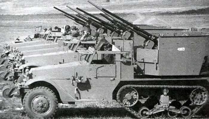
During July 1942, the Services of Supply, at the request of Armored Force, issued a memorandum to obtain 80 improved self-propelled 37 mm guns to be used in an anti-aircraft and anti-ground role to be used in a special mission. To accomplish this, the Ordnance Board issued ‘OCM 18477’ to create 80 vehicles using the M3 Half-track as a base. These had the troop compartment’s sides and rear armor removed and a mount placed centrally. They would receive the designation Motor, Carriage, Combination Gun T28E1. Production of these began by Autocar in July 1942 and lasted till August.

The 78 T28E1s, with the remaining two kept to facilitate experiments, were issued to the 443rd Anti-Aircraft Artillery (AAA) Battalion in September 1942. These were split into four batteries of 20 vehicles, with the fourth company, D Company, receiving two towed 40 mm guns to give it 20 guns. The T28E1s were actively deployed in the Tunisian Campaign during 1942 and 1943, where they shot down around 78 planes, mostly Ju-87 Stuka dive bombers. Following the end of the campaign and the war in North Africa, they were deployed alongside M15 CGMCs until the end of the war, with vehicles being replaced by M15s when necessary.

After an examination by the Anti-Aircraft Artillery Board, the original T28 and the T54, a half-track armed with a 40 mm gun, were deemed unsatisfactory. Nevertheless, the T28 was considered to be more advanced. As a result, the Board decided that the T28 would be useful as an expedient weapon (an expedient weapon was an improvised device, sometimes created by soldiers in the field) if it was modified mainly by using the M3 Half-track and the air-cooled, heavy barrel version of the 12.7 (0.5 in) machine gun using an improved firing mechanism. The other changes, mainly in ergonomics and protection, included:
- larger hand wheels
- moving the vertical and lead setters’ hand wheels
- improving the boresighting equipment
- extending the depression to -5°
- a mechanism to collect and dispose of empty cases
‘OCM 19087’ of 29 October 1942 incorporated these changes and designated the vehicle as the Carriage, Motor, Combination Gun, M15, and it was recommended to be classed as a Substitute Standard, a piece of equipment used to fill a role temporarily until better equipment was available.
The recommendation for the M15 to be classified as a Substitute Standard gained approval during November 1942, with production being approved to meet requirements for such vehicles in North Africa. The M15 pilot vehicle was manufactured at the Autocar Company, with its evaluation taking place from December 1942 to January 1943 at Aberdeen Proving Ground. This resulted in the gun shield being removed to increase visibility and the amount of 37 mm ammunition to be increased from 140 to 240 rounds. Production lasted from February to April 1943.

After the T28E1 and M15 were successfully employed in North Africa, demonstrating to the US that there was a need for more M15s. However, the M3E1 gun carriage that the M42 mount was based on was no longer available. To remedy this, it was decided to adapt the M3A1 gun carriage, of which 1,750 were available, combined with the M6 sighting system that created the combination gun mount T87. ‘OCM 21226’ designated this M3A1 gun carriage-based vehicle as the M15E1.
On 12 August 1943, ‘OCM 21281’ standardized the new vehicle as the Carriage, Motor, Combination Gun, M15A1, with this being approved in September 1943. The main changes were using the M54 combination gun mount that located the M2 machine guns below the 37 mm M1A2 and decreased the amount of ammunition carried.

In October 1943, the production of the M15A1 began, lasting until February 1944, with 1,652 M15A1 produced. However, as production was ending, on 24 February 1944, ‘OCM 23270’ was issued, recommending standardizing the M14 computing site for use on the M15A1.
On paper, the end of the M15A1 service began on 12 July 1945, after a recommendation for the M15A1 to be reclassified as a Substitute Standard, which was approved in August 1945. However, the M15A1 would continue to serve until the Korean War, during which it finally left service.
Design
General Dimensions
The M15 CGMC’s total combat weight was 9.1 tonnes (10 tons), with a tyre ground pressure of 2.35 kg/cm2 (33.5 psi). The full-length was 6 m (236.5”), width 2.5 m (98”), height 2.64 m (104”), wheelbase 3.442 m (135.5”), front tread 1.64 m (64,5”), rear tread 1.62 m (98”), and ground clearance 28.4 cm. The pintel height was 71 cm (28”).

Armor
The M15 CGMC’s armor was bolted and made out of rolled face-hardened steel. The armor was 6.4 mm (0.25 in) thick on the radiator louvers (at 26° from vertical), sides, rear, hood top (at 83° from vertical), and gun shield. The windshield cover was 12.7 mm (0.5 in) at 25° from vertical.

Suspension
The M15 CGMC’s front suspension consisted of a semi-elliptic longitudinal leaf spring with shock absorbers and steel ventilated disc brakes.
The rear suspension was a vertical volute spring with one bogie with four road wheels and with one return roller on top of the bogie. The tracks used an eighteen-tooth sprocket, and the idler wheel was spring-loaded. The track was of the Kegresse type, being made in one piece, mostly out of rubber. This gives a turning diameter of 1,828 cm (60’).

Powerplant, Automotive Systems, and Performance
The M15 CGMC used a White 160AX four-cycle, in-line petrol, six-cylinder engine. It developed 147 hp at 3,000 rpm, with 325 ft-lbs of torque at 1,200 rpm, a cruising range of around 320 km (200 mi) on the road with a consumption of 1.48 liters per kilometer (3.5 miles to the gallon). The maximum speed was 72 km/h (45 mph).
| First gear (km/h) | Second gear (km/h) | Third gear (km/h) | Fourth gear (km/h) | |
|---|---|---|---|---|
| Without powering the front wheels through the transfer case | 14.72 | 27.84 | 42.16 | 72.42 |
| With front wheels and the transfer case powered | 5.92 | 11.20 | 16.82 | 29.05 |
| First gear (mph) | Second gear (mph) | Third gear (mph) | Fourth gear (mph) | |
| Without powering the front wheels through the transfer case | 9.15 | 17.3 | 26.2 | 45 |
| With front wheels and the transfer case powered | 3.68 | 6.96 | 10.45 | 18.05 |

The M15 CGMC’s steering used a wheel and hydraulic brakes. The M15 CGMC used a Spicer 3461 constant mesh transmission, with four forward speeds and one reverse. The M15 CGMC could overcome 304.8 mm (12”) high obstacles with a maximum grade of 60% and ford depths of 81.3 cm (32”), with a turning diameter of 1,828 cm (60’).
The fuel capacity was 227.1 liters (60 gallons) in a fuel tank behind the cab. The upper fuel tank was behind the driver, with the lower fuel tank under the floor near the upper fuel tank. The filler caps were located centrally behind the cab.


Armament
The M15 and M15A1 used the M1A2 37 mm anti-aircraft gun and M2HB 12.7 mm (0.5”) machine guns using various mounts and sights. The 37 mm gun ejected rounds from the bottom of the weapon. When attempting to shoot down planes, the machine guns were used to track the target, and only once the machine guns hit the plane, would the 37 mm gunfire. Another tactic used by US crews was to fire the machine guns at a plane which was out of range of the machine guns but still within range of the 37 mm gun to lull the pilot into a false sense of security, thinking they were relatively safe before firing the 37 mm gun to down the plane.


| Model | Weight of the round | Length of the round | Warhead Contents | Muzzle velocity | Range | Tracer burn length |
|---|---|---|---|---|---|---|
| M54 HE W/Tracer | 1.19 kg (2.62 lb) | 32.54 cm (12.81 in) | Tetryl bursting charge | 792.48 m/s (2,600 f/s) | 3,200.4 m (3,500 yd) | 8 s 3,200.4 m (3,500 yd) |
| M57 and M57A1 HE W/Tracer | 1.19 kg (2.62 lb) | 32.54 cm (12.81 in) | Tetryl bursting charge | 792.48 m/s (2,600 f/s) | 3,200.4 m (3,500 yd) | 8 s 3,200.4 m (3,500 yd) |
| M74 AP W/Tracer | 1.39 kg (3.07 lb) | 33.05 cm (13.01 in) | Solid | 624.84 m/s (2,050 ft/s) | 7,290.4 m (7,290 yd) | 1828.8 m (2,000 yd) |
| M59 Fixed Shot | 1.42 kg (3.12 lb) | 32.41 cm (12.76 in) | Solid | 624.84 m/s (2,050 ft/s) | 5,790 m (5,790 yd) | 5294.38 m (5,790 yd) |
| M55A1 Practice Round | 1.19 kg (2.63 | 32.54 cm (12.81 in) | No Explosive Elements | 792.48 m/s (2,600 f/s) | 8115.3 m (8,875 yd)>/td> | 8 s 3,200.4 m (3,500 yd) |
| M21 Drill Cartridge | 1.21 kg (2.67 lb) | 32.54 cm (12.81 in) | N/A |
Crew
The M15 had seven crew members. All directions are from the vehicle’s front view:
- the commander was located on the left side of the driver’s compartment
- the driver was located on the right side of the driver’s compartment
- the lead setter (gunner) sat behind the gun, with a vertical gunner on the left side of the mount, and a horizontal gunner on the right side of the turret
- the two cannoneers (the artillery term for a loader) sat in the turret’s front, on either side of the guns. They were in charge of loading and clearing stoppages

The driver acted as the radio operator when the vehicle was stopped or firing, with the commander acting as the radio operator when on the move. The two cannoneers fed the guns with ammunition and kept them operational. The gun pointers each had a telescope located 30.5 cm (1 ft) away from their dominant eye. While looking through the telescope, they kept both eyes open. The vertical gunner was in charge of firing and had a pedal for firing the 37 mm gun on the left and a pedal to the right, which fired the machine guns. The lead setter was second in command and adjusted the lead on the sights using the tracers to achieve a hit with the 37 mm.
The crew communicated using an SCR 510 radio and had four 7.62 mm (0.3 in) carbines (presumably M1 carbines) in addition to their M1911 pistols, which were likely issued.

Variants
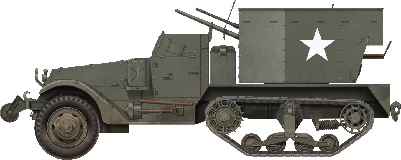
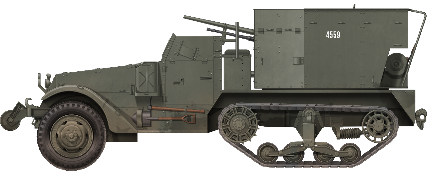
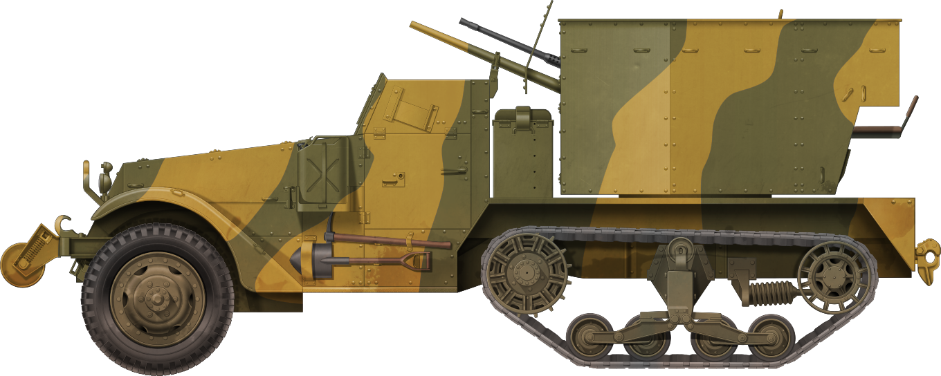
M15 Combination Gun Motor Carriage
This was the initial version of the M15, based on the M3 Half-Track chassis. In total, 680 M15s were produced from February 1943 until April 1943. Compared to the T28E1 machine guns, water-cooled M2 12.7 mm (0.5 in) machine guns were changed to air-cooled versions on the M15, a gun shield with stowage was added around the gun platform, and a separate gun shield was placed around the gun barrels. The shield had an open back with flat sides and diagonal corners. These modifications increased the weight, which caused a decrease in reliability and mobility.

The M15 used the M42 weapon mount, which allowed for a traverse of 360° and an elevation from 0° (20° above the cab) to 85°. The gun mount was descended from the M3E1 gun carriage. The gun shield rotated with the weapon mount, as it was fixed to the mount.

Image Source: https://brookehurst.blogspot.com/p/weapons-and-vehicles.html


There were 240 rounds of 37 mm ammunition for the main gun and 3,400 rounds for the 12.7 mm (0.5 in) ammunition for the two machine guns. Of the 37 mm gun rounds, 140 were stored in boxes behind the cab and the remaining 100 were held within the gun shield.


The gun used the M6 sighting system, which consisted of the M7 telescope for tracking, an M64 telescope for elevation situated to the right, and a vertical and horizontal deflection mechanism with a mount to fix it to the main gun mount. The 1x telescopes had an 11° field of view and illumination at night. The deflection mechanism was operated by a handle which was pushed left and right while pushing up or down. It was vital that the lead setter kept their hand on the lever, as not doing so could inadvertently change the vertical lead-in.

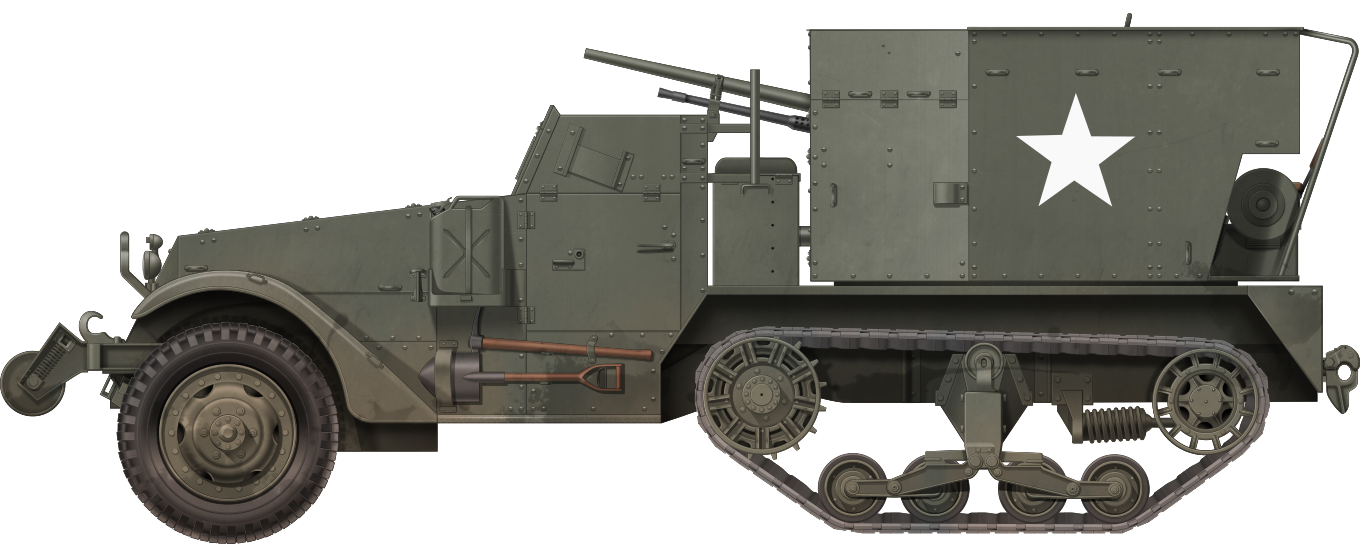
M15A1 Combination Gun Motor Carriage
Due to the stocks of the M3E1 Gun Mount running dry, surplus M3A1 37 mm anti-aircraft gun carriages modified with two M2 machines were mounted on the back of the M15 to create the M15A1. As approximately 1,750 of these mounts were available, this saved time, resources, and money. The most obvious change from M15 to M15A1 was the machine guns being relocated due to the new mount (M54 combination gun mount), which allowed for a traverse of 360° and an elevation from 0° to 90°.

Other changes included the M14 computing site, folding shields on the front of the gun shield, and removing the shield around the guns. The ammunition was also reduced to 200 rounds of 37 mm ammunition for the main gun and 1,200 rounds for the 12.7 mm (0.5”) ammunition for the two machine guns. These improvements led to the most numerous production runs, with 1,652 M15A1 CGMCs built between October 1943 and February 1944, with 1,052 built in 1943 and 600 built in 1944.


The estimated speed of the target aircraft was input into the targeting computer using speed setting knobs, and this caused the speed slider, which was controlled in 25 mph (40 km/h) increments from 0 to 525 mph (845 km/h). The target aircraft’s horizontal path was input so that the target path arrow aligned with the target. The vertical path was tipped to the appropriate direction of the plane. The target was centered on the reticle in the azimuth and elevation telescopes. The computing sight could be locked on specific geometries. If the sight was not set up correctly it could destroy parts of the sights.

https://www.reddit.com/r/ww2/comments/u2y5kt/26th_infantry_division_crew_of_an_m15_multiple/

Image source: https://old-forum.warthunder.com/index.php?/topic/559722-jgsdf-m15a1-cgmc/
M15 “Special”
The M15 “Special” was a half-track mounted with a 40 mm Bofors gun. A variety of half-tracks were converted, although sources disagree about whether the M15 chassis was also used, although this seems unlikely as the 37 mm gun would serve a similar purpose to the 40 mm gun.
The recoil was too strong to be effective in an anti-aircraft role, resulting in it being used in a ground support role. These conversions were performed by the Coopers Plains 99th Ordnance Depot near Brisbane, Australia. The Bofors guns were placed in an eight-sided turret. The M15 “Special” was deployed to Luzon, the largest and most populous island of the Philippines, with the 209th and 447th AAA Battalions.

| Autocar M15 and M15A1 CGMC Production | |||||
|---|---|---|---|---|---|
| Date | T28E1 | M15 | M15A1 | Ordnance Serial Numbers | Registration Numbers |
| July 1942 | 20 | 1 – 20 | 4053380 – 4053399 | ||
| Aug 1942 | 60 | 21 – 80 | 4053400 -4053459 | ||
| Feb 1943 | 227 | 81 – 307 | 4083287 – 4083513 | ||
| Mar 1943 | 272 | 308 – 579 | 4083514 – 4083785 | ||
| April 1943 | 101 | 580 – 680 | 4083786 – 4083886 | ||
| Total | 80 | 600 | |||
| Oct 1943 | 100 | 682 – 781 | 40149399 – 40149498 | ||
| Nov 1943 | 500 | 782 – 1281 | 40149499 -40149998 | ||
| Dec 1943 | 452 | 1282 – 1733 | 40149999 – 40150450 | ||
| Jan 1944 | 420 | 1734 – 2153 | 40150451 – 40150870 | ||
| Feb 1944 | 180 | 2154 – 2333 | 40150871 – 40151050 | ||
| Total | 1,652 | ||||
Table sourced, with slight modifications, from https://www.usautoindustryworldwartwo.com/autocar.htm
Service
United States
The M15 entered service in autumn 1943, serving alongside the M13 MGMC and later the M16 MGMC. Where possible, if both vehicles were present, the M15s would provide longer-range fire, while the M13s and M16s would provide close range cover.
The M15 first served in Italy, alongside the T28E1 and M13 MGMC. Armored divisions were given anti-aircraft companies, each with eight M15s and eight M13/M16. They also served at Corps and Army levels, each receiving thirty-two M15s and an equivalent amount of M13 or M16s. These protected high-value areas or objectives, such as bridges, rail junctions, or headquarters.


The M15 served during the D-Day landings, with some landing during the initial operations. The type then served throughout the Northwest European campaign. However, the Luftwaffe was no longer a significant threat, so the M15 was used in the infantry support role. It participated in the Battle for Bastogne, during the last major battles with the Luftwaffe, which resulted in the M15 again serving as an anti-aircraft weapon from the end of 1944 to early 1945.


The M15 served during Operation Dragoon, the 1944 invasion of the south of France, where it initially defended the beachheads against the Luftwaffe.

Image Source: https://s3.amazonaws.com/NARAprodstorage/lz/stillpix/111-sca/Normandy/111-SC-192870.jpg
The M15A1 MCMG saw limited use in the Pacific, with some used during the recapture of the Philippines, particularly on the island of Luzon and the Battle of Okinawa.

The M15A1 also served as an infantry support vehicle during the Korean War, alongside the M16, after which it was phased out.
Other Users
USSR

The USSR received 100 M15A1s via Lend-Lease and was the only nation to do so. Little is known about their service.


Yugoslavia


Yugoslavia received 20 M15 and M15A1 CGMCs via the Mutual Defense Assistance Program (MDAP) during the short window of collaboration between the Communist nation and the USA. These served in the anti-aircraft batteries of three armored brigades. These were turned over to territorial defense units in the early 1970s.

Japan

Japan received around 181 M15 CGMCs. These were given to Japan after the end of the Korean War. They served from 1950 to 1991.

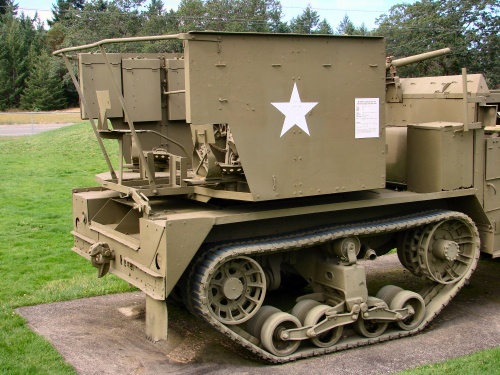
Surviving Vehicles
Approximately 18 vehicles survive, with two M15 CGMCs in the US. Chassis number ‘86’ is located at the National Museum of Military Vehicles in DuBois (Pennsylvania), and the other at Gary’s Half-Track Parts in Lamont (California) (as of 23 February 2023).

There are 15 M15A1 CGMCs known to have survived. Thirteen intact and one wreck are in the US, which are largely in museum condition or otherwise good condition, one in the Military Museum in Kačarevo, Serbia, and a weathered example is at an unknown military ground somewhere in the former Yugoslavia.


An M15 “Special” is also in the National Museum of Military Vehicles, DuBois.

Conclusion
In summary, the development of the M15 CGMC and its variants represented a significant advancement in American anti-aircraft capabilities. Stemming from the need for mobile ground anti-aircraft platforms, these vehicles underwent a series of modifications and improvements based on field experiences and technological advancements. Throughout their service, these vehicles proved their worth in various theaters of war, including North Africa, Europe, and the Pacific. Initially used for anti-aircraft defense, they later found utility in infantry support roles as the threat from enemy aircraft diminished. Beyond World War II, the M15 and M15A1 CGMCs continued to serve, albeit in limited capacities, during the Korean War before being phased out of service.

M15 and M15A1 CGMC specifications |
|
|---|---|
| Dimensions (L/w/h) | Length: 6 m (6.57”) Width: 2.5 m (2.72) Height: 2.6 m (2.89”) |
| Total weight, battle ready | Between 9.1 tonnes to 9.4 tonnes (10 tons to 10.4 tons) with the difference between variants negligible |
| Crew | 7: a commander, driver, lead setter (gunner), vertical gunner, horizontal gunner, two cannoneers |
| Engine | 147 hp White 160AX four-cycle, in-line petrol, six-cylinder |
| Suspension | Front: Semi-elliptic longitudinal leaf spring Rear: Vertical volute |
| Top speed | 72 km/h (45 mph) |
| Range (road) | 320 km (200 mi) |
| Armament | M1A2 37 mm anti-aircraft gun 2 M2 12.7 mm (0.5 in) HB machine gun |
| Armor | 6.4 mm (0.25 in) to 12.7 mm (0.5 in) |
| Total production | M15: 600 M15A1: 1,652 |
Sources
War Department, SELF-PROPELLED ANTIAIRCRAFT AUTOMATIC WEAPONS
Other title: Film Bulletin, no. 88, 1943, via https://catalog.archives.gov/id/24492
War Department, TM9-710, 1944
Catalogue of Standard Ordnance Items, second edition 1944, volume I: Tank and Automotive. Washington, D.C.: Office of the Chief of Ordnance, Technical Division, 1 June 1945, Page 30
RP Hunnicutt, 09. Half-Track – A History of American Semi-Tracked Vehicles, Presidio Press, Novato, 2001
ED Michael Franz, № 6010 – US WW2 Half-Track, Erlangen, Tankograd Publishing, 2007
Steven J Zolaga, 011 – M3 Infantry Half-Track 1940-73, Osprey Publishing, Oxford, 1997
Jem Mesko, M3 half-track in Action (Armor Number 34), Squadron/ Signal Publications, Carrollton, 1996
Bojan B Dimitrijevic, Tankograd 7023: Armoured vehicle of the Yugoslav armies 1945-present, Erlangen, Tankograd Publishing, 2011
Steven J. Zaloga, 247 – Soviet Lend-Lease Tanks of World War II, Osprey Publishing, New York, 2017
Rickard, J (23 May 2014), M15 Combination Gun Motor Carriage, date viewed 08 January 2024, http://www.historyofwar.org/articles/weapons_M15_CGMC.html
Chris Conners, Multiple Gun Motor Carriage M15, American Fighting Vehicle Database, date viewed 08 January 2024, http://afvdb.50megs.com/usa/mgmcm15.html
Chris Conners, Multiple Gun Motor Carriage T28E1, American Fighting Vehicle Database, date viewed 08 January 2024, http://afvdb.50megs.com/usa/pics/mgmct28e1/mgmct28e1.html#LF884
David D Jackson, The American Automobile Industry in World War Two, us auto industry world war two, date viewed 08 January 2024, https://www.usautoindustryworldwartwo.com/autocar.htm
Unknown, http://infoseek_rip.g.ribbon.to/muwsan.hp.infoseek.co.jp/phot-m15a1.htm, “実車写真館 陸上自衛隊 37mm 自走高射機関砲 M15A1” Actual vehicle photo studio Ground Self-Defense Force 37mm self-propelled anti-aircraft gun M15A1, date viewed 11/01/2024