
 Commonwealth of Australia (1942)
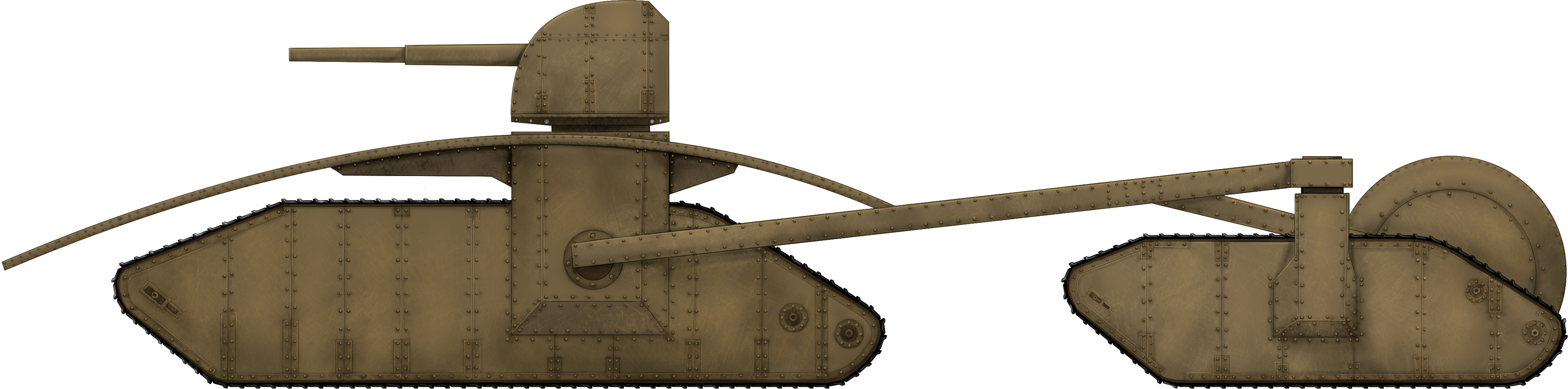
Heavy Tank – None Built
Post WW1, most tanks follow a common enough shape, with a rigid armored body, a pair of track units, with one on each side, an engine located within the body, and either a fixed casemate gun or a turret with some secondary guns in the hull. When a vehicle diverts from this common type of layout, it stands out and few designs could be seen as diverting from the norm as much as the triangular multi-tracked tank from the pen of Lance Bloomfield of New South Wales, Australia in 1942. In this design, Bloomfield diverted from the norms of tank design in virtually every conceivable way.
The Men Behind the Design
The designer behind the vehicle was Lance Bloomfield who, in signing the letter which accompanied the sketches, was sure to add that he was an “Old Digger”, meaning he had formally served in the Australian forces previously, most likely in WW1, which might partially explain the general shape of the primary drive unit.
Providing an address at Roslyn, Garland, in New South Wales, he came from a very rural area West of Sydney and appears to have led a rather uneventful life. However, his design and letter were not sent in by him, but on his behalf by Mr. W. Bloomfield, also of Garland, New South Wales, with instructions to send all return correspondence via W. Bloomfield. The family name matching suggests a direct relative but there is no mention of the exact relationship. The date on the design, as drawn by Lance Bloomfield, was 1st July 1942, but it was not submitted until 13th July. The submission was left with the Army Office in Sydney and then sent on to the Army Inventions Directorate on the 18th.
Design
Layout, Engine, and Suspension
The general layout of Bloomfield’s design was a triangle with a primary caterpillar to be made from 2 or 4 separate tracks, forming a single 4’ (1.2 m) wide contact surface which was the forward point of the triangle. A pair of secondary tracks were each connected by a beam coming from the rear third of this central primary track unit and were held level using a trailing wheel between these two secondary units and which was itself held in place by an arm coming from the center of each of the beams from the primary to secondary track, forming a diamond shape within the overall triangular shape of the machine. The single track unit at the front was to provide the primary propulsion for Bloomfield’s “very heavy tank” and to contain the engine in the rear half, along with the gearing behind it and driving a rear track sprocket with the power transmitted by means of a gearbox to a crown wheel and pinion with no differential.

Source: Australian Army Inventions Directorate file 4932, 40.
Unusually, the sprocket was to be in contact with the ground at the back. No particular engine or even type of engine (petrol or diesel) was specified by Bloomfield. With no engine shown in the secondary units, it is likely that he was proposing some kind of power take-off from the gearbox to be taken out to these secondary units. Such an arrangement of power transfer would be complicated but would allow for easy steering of the machine given how far apart the two units were, alluded to in his description stating that the design would be able to turn within its own length.
The overall shape of the primary drive unit under the armor was similar in some respects to the quasi-rhomboidal shape of British tanks in WW1, with the exception that the front was formed in a sharp triangle shape. Large wheels were positioned at the change in angle of the track as it ran around the circumference of the body and held off by means of 17 small wheels or rollers, for a total of 22 wheels or rollers to support the track.
Within this body, the power and transmission would all be at the front and extending to around the halfway point with the turret, with the remainder of the space behind it all assigned for stowage and fuel.

Source: Australian Army Inventions Directorate file 4932, 40.
Armor
Bloomfield neither specified nor drew a thickness of armor for the design, but he did draw and describe the shape. He specifically wanted armor sufficiently thick to deflect “all field artillery that is used with open sights” and drew an armor layout consisting of a large upturned shallow oval bowl with the armor held off from the body of the vehicle and projecting beyond the vehicle on all sides and curving down to just above ground level to provide complete sheltering for the main section.
Whilst this shape did provide a very curved slope which would improve the chances of causing a shell deflection, it had the serious problem that it would hinder the mobility of the vehicle. Projecting as it did so far fore and aft, the shielding would inevitably foul on the ground or on obstacles such as tree stumps or rocks or embankments, despite his idea that hydraulic joists would be able to raise it slightly.
No armor is shown or mentioned for either of the two supplementary tracks connected to the main vehicle. Neither, for that matter, is any mention made of protection for the primary vehicle itself. Whilst the vehicle’s full width would be covered by the moving tracks, the sides would not and it can only be assumed that some sort of protection was envisaged here as well, or else it would lead to a very poorly protected and vulnerable vehicle inside.
Firepower
Bloomfield wanted the vehicle to “carry a gun that will blast anything on the battlefield” and, to this end, he noted the primary weapon located centrally in what appears to be a turret on the primary track unit as a “4 or 6 inch” naval gun”.
In the front of the hull of this primary unit were a pair of holes through the armor for a pair of ‘lighter guns’, followed by a row of three more holes marked for machine guns. This would mean the ‘lighter guns’ were envisaged as something between a machine gun caliber weapon (the standard British Empire machine gun of the day being .303) and a 4” naval gun, which left a lot of room to select an armament.
This was not the end of the firepower for Bloomfield’s design either. On the rear of the hull, facing backwards, was a single, centrally located ‘light gun’ followed by two more machine guns lower down. This meant a grand total of one main gun, 3 intermediary guns, and 5 machine guns. It is wholly unclear whether these lighter guns or machine guns were to be operated directly or by some remote firing device or if the method of operation was even a consideration, but the combat value of fixed weapons like this is very limited, especially fixed in position to the rear. The turret-mounted primary weapon, on the other hand, would have been a monster. The monobloc 4” QF Mk. XIX gun of the era weighed well over a tonne on its own and was capable of firing a 15.9 kg High Explosive shell at nearly 400 m/s out to nearly 9 km. The 6” BL Mk. XXIII was even larger, weighing nearly 7 tonnes, and was capable of firing a 50 kg High Explosive shell at 841 m/s in excess of 23 km.

Source: Australian War Memorial
Both of those guns saw service with Australian forces during the war. However, the servicing of such guns was a huge task. The 4” Mark XIX required 6 men to operate it properly, with 3 men needed to keep bringing the ammunition to the gun to keep up with the maximum rate of fire of 15 rounds per minute. Each shell with its propellant weighed over 22 kg, meaning a single minute’s ammunition at the maximum rate of fire meant ⅓ tonne of ammunition being spent. Estimating perhaps 50 rounds provided for the gun to be a useful combat load, this would still mean over a tonne of ammunition. The situation would be even more extreme using a 6” gun, like the Mk. XXIII, as each complete round weighed over 60 kg including propellant, meaning that 50 rounds would mean 3 tonnes of ammunition along with the nightmare of moving such a heavy shell by hand in the confines of a tank turret.
Whilst a 4” gun might be a little excessive for dealing with enemy tanks and positions, it was still viable as a hand-loaded weapon for the vehicle, but the 6” option was a step too far and both impractical and unnecessary.

Source: Australian Army Inventions Directorate file 4932, 40.
Rejection and Conclusion
It is perhaps not a surprise that the vehicle design did not reach the level of approval or production. It was too different and too flawed. The rejection process only took a few days, with a formal reply on 25th July 1942 saying that “..after thorough investigation by our technical officers, the decision has been reached that the suggestion submitted by you cannot be accepted”. Perhaps it was just due to the overall concept of a three-hulled vehicle which would mean too much design and testing work to carry off during a war.
The design was seriously flawed too, for a variety of reasons, some of which no doubt the Inventions Directorate considered and some others which maybe are clear only in hindsight. Whatever their reasons were, the Army did not expand on them, just thanking Bloomfield for his suggestion and closing the file on it.
The single front unit provided little effective fighting space for the crew, the fixed weapons were adding weight but little combat potential. The three hulls attached to each other the way that they were, added enormous complexity to the vehicle, but would also seriously hinder maneuverability of the vehicle off-road, through trees, or past other obstacles but much more than that in terms of moving along roads or being hauled by railway.
The armor too was an obvious problem and let the whole design down. The concept of connecting the individual parts of the vehicles together in such a way and balancing them with the trailing wheel was sound enough, although whether a system of powering them could be installed is another issue. The armor, however, formed as it was in that large shallow bowl shape, meant that the vehicle would inevitably foul on even modestly undulating terrain and it was not efficient either. So little of it overhung the sides that it left the vehicle underneath less well protected than it would be if the armor had simply been concentrated on the body of the track units instead.
Specifications Bloomfield’s Tortoise Single Track Heavy Tank |
|
|---|---|
| Crew | unknown |
| Dimensions | main caterpillar 4’ (1.2 m wide) |
| Armour | heavy |
| Armament | 5 x machines guns, 3 x light guns, 1 x 4” or 6” naval gun |
| Engine | unknown |
| Speed | unknown |
Sources
Australian Army Inventions Directorate file 4932, 40. Dated 16th October 1942
Government Gazette of the State of New South Wales 6th December 1940
Navweaps.com
One reply on “Bloomfield’s ‘Tortoise’ Single Track Heavy Tank”
It’s as if the designers placed signs on the tank reading: “Don’t Shoot At Me, I’m Terribly Impractical!”