 United Kingdom (1916)
Tank – Design Only
Prior to World War One, the Lincolnshire-based firm of William Foster and Co. Ltd. had primarily been a manufacturer of agricultural equipment and heavy tractors. It was the frightful slaughter of that war which brought ideas of using modern mechanical traction machines based on wheels, tracks, or both to the fore. The British had got their first tank on the battlefield just ahead of the French, but with very different machines. The French had based theirs off of modified agricultural tractors. The British too had started this way but, by Autumn 1915, had moved from repurposed existing tractors to a new type of track system from the pen of Sir William Tritton and Major Walter Wilson. That was the track system used on the first British tanks, large flat steel plates riveted to a steel shoe and running around the outside of the tank, producing one of the most distinctive vehicle shapes in warfare. Those early quasi-rhomboidal tanks were not the only tracked designs from William Foster and Co. Ltd., which continued to experiment with ideas over both tracked vehicle layouts, protection, firepower and moving back to concepts of armored personnel carriers. One of the results of this experimental work might be considered the ultimate WW1 design, known as the ‘Battletank’.
Conceptualization
The design of the Battletank followed directly from the ‘Flotilla Leader’ of April 1916. following the same conceptualization of what was needed from a tank and how it would work. Specifically, the vehicle was to be as protected as possible against enemy fire, specifically enemy field gun and artillery shells, whilst still being able to cross broken terrain and obstacles. In fact, obstacle crossing was to be better than that of the Mk.I, it was to have more firepower than the Mk.I to better assail enemy positions, and potentially carry a storming party of infantry.
The 28 tons (28.4 tonnes) Male version of the Mk.I was armed with a pair of 6 pounder guns mounted in sponsons, with one on each side, along with machine guns, whereas the Female version was armed only with machine guns. Both were powered by the same 105 hp 6 cylinder Daimler sleeve-valve petrol engine. Able to cross a 10’ (3.0 m) wide trench, and climb a vertical step (or parapet) 4’ 6” (1.4 m) high, they were protected by armor up to 12 mm thick. This was enough armor to protect against rifle bullets but still vulnerable to concentrated machine-gun fire and field guns.
Even prior to the combat debut of the Mk I in September 1916, design work and development had been continuing to try and improve on this early vehicle. The shape of the Mk I had been meant to allow it to cross obstacles effectively by raising the height of the track on the leading face of the vehicle. The disadvantage had been that a lot of weight was concentrated on the rear sections of the tank with the raised nose off the ground. A longer flatter track run would resolve this, but a raised section of track at the front necessitated a second track, even an unpowered one. The increased weight of the tank and in order to improve mobility, a set of auxiliary tracks had also been added and all of those features went into the Flotilla Leader in April 1916.
That design had substantially increased armor protection too, with an increase from 12.7 mm up to 50 mm, and firepower improved with additional machine guns matched with increased weight and a second engine.
The tactical employment concept for this new vehicle is unclear, but the names of both Flotilla Leader and Battletank imply the use of this vehicle leading an assault of other vehicles.
The Flotilla Leader
The Flotilla Leader design embodied the desire for more of everything, from firepower to armor. It was dominated as a design by an angular casemate that projected above and ahead of a lower-body and featured a pair of large sponsons projecting wider than the hull at the front.
A short vertical section of track ran from just below the level of the main guns in the sponsons to just above ground level between the two main tracks and would be the first section of track to reach the other side of an obstacle and prevent the vehicle from digging into the opposite bank.
The casemate was the main fighting chamber, behind which was a long and lower hull with vertical sides and an angled rear end. Within, the hull space was clearly allotted for troops along each side and as suggested by the plans. Any troops inside the hull would be able to fire out of loopholes in the sides. The rear hull was narrower than the casemate at the front and the 2’ (0.6 m) difference was made up by a gangway running the full length of the hull body, which went over the tracks and from the edge of which would be suspended armor plating covering the tracks. Troops inside could dismount the vehicle from this gangway. The powerplant, a pair of 105 hp Daimler engines, was located just aft of the center of gravity inside the hull and provided drive to both the primary and auxiliary tracks. A pair of trailing wheels were fitted to the back of the tank.

Source: Stern Archives
Flotilla Leader to Battletank
The April 1916 Flotilla Leader was designed when the new technology of tanks was not even in its infancy. The machines existed, they were driven, they could be tested in anything other than combat situations. Until September 1916, this combat experience was almost guesswork for the designers. What this also meant was that there was time to rethink the concept of the Flotilla Leader from perhaps merely leading an assault to being the main type of tank itself. As the concept was worked through, changes were made to improve mobility and fightability of the design, but many of the features from the Flotilla Leader would remain with this new vehicle. It was christened the ‘Battletank’ in July.

Source: Stern Archives
Between April and July 1916, the design of the Flotilla Leader was tweaked and improved. The man behind these changes was William Rigby and this is indicated by his initials on the blueprints next to the date of completion, 13th July 1916. They were finalized as William Foster design 105V, clearly labeled ‘Foster’s Battletank’.

Source: Stern Archives.
Layout
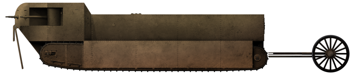
The layout of the Battletank was much the same as that of the Flotilla Leader. It had a large superstructure with a raised front casemate containing the primary armament. The essential shape remained the same, with a large angled sponson on each side of the nose. Whereas this ‘nose’ on the Flotilla Leader’ was made up of separate sections of armor forming a very angular appearance, the Battletank had a large curved section. This was a better shape ballistically and potentially also one that could have been cast in one piece. The step at the back of the casemate was no longer vertical but angled to the flat roof of the main hull. This ran flat all the way to the back of the tank, where it met the vertical rear end.
Two long primary tracks ran the full length of the machine on each side, with the same style of walkway above them and hanging armor plates over the side. The second set of tracks were fitted at the back, along with a set of trailing wheels. The tertiary track at the front of the Flotilla Leader was gone and replaced with a double thickness heavy armor panel to protect the front.
The total machine measured 43’ (13.1 m) long from nose to the back of the trailing wheels and 32’ 6” (9.9 m) without them. At 9’ (2.7 m) high and 13’ (4.0 m) wide, it was still not a small vehicle. It had, in fact, gotten longer. The hull was the same length but the overall length had grown 3’ 6” (1.1 m) with the extra length from the trailing wheels, so as to allow them to move upwards without fouling on the tank’s rear hull.
Suspension
No speed was specified or recorded for the Flotilla Leader in April 1916 or the July Battletank. sketch. The only note of assistance was the weight – some 45 tons (45.7 tonnes). This weight would be borne by a pair of track running along a very low and flat track from an idler at the front, under the sponson main gun position to the rear. This measured 26’ (7.9 m) from front to rear, but only 9’ (2.7 m) of it would be in contact with the ground when on a hard surface. If the vehicle began to sink into soft ground, the amount of track in contact with the ground would increase proportionally to spread the load. Each of these primary and auxiliary tracks was to be 2’ (0.6 m) wide.
No system of springing for shock absorption was provided – none of Tritton’s designs featured springing suspension but cushioning from vibration was a function of the rollers in Timken bearings running on the track. A relatively slow speed, perhaps not more than just matching the Mk I at 3.7 mph (6.0 km/h), did not necessitate the complexities of adding springs into a system.
Extra Tracks
Those supplemental rear tracks, a feature carried over from the Flotilla Leader, would continue on the Battletank and are described by Tritton explicitly as an “auxiliary [sic] driving system”. Specifically, these tracks were not just to assist in crossing obstacles, but were powered. In November 1916, then William Tritton (he was knighted in 1917 for his work on the development of the tank) submitted a patent application for “Improvements in and relating to Transport Vehicles Propelled by an Endless Moving Chain Track or Tracks”. Euphemistically written to avoid mention of ‘tanks’, the explanatory description and drawings within the patent make it clear as to why these tracks were designed and what they were meant to do.
The tracks themselves were essentially just smaller and shorter versions of the primary tracks fitted onto a centrally pivoting point and driven by chains from the primary gearbox. These tracks measured about 7’ 6” (2.3 m) long. The driving chains for these tracks, would, in fact, be the same one as driving the primary sprockets for the tracks sharing a common axle as the point around which these two auxiliary tracks could rotate.

Source: British Patent GB126070
All four tracks (2 long primary and 2 short auxiliary tracks) would usually be driven at the same time. Tritton, in his patent, describes a potential future modification may be to drive them together or separately but, as drawn in July 1916, they would be running at the same time and speed as the primary tracks. On a good surface, like a road or hard ground, it might be supposed that these tracks, not being in contact with the ground, would simply rotate in thin air, but this is not correct. Being pivoted around their central axle and driven by a sprocket attached to and projecting past the center point of the axle would induce a rotational moment on the whole unit, causing them to tip forwards and down until they reached the ground. The opposite would be true in reverse, where the rear end of the track would pivot down until it reached the ground. Thus, even on a good surface, at least one end of this auxiliary unit would be in contact with the surface, providing additional traction.
This dynamic of how the unit would move when subjected to a driving force was particularly valuable when considering the vehicle as one crossing very rough ground. In the case of climbing a bank, the long primary unit would, as it reached the crest, progressively lose ground contact and thus traction. Not only that, but with a reduced bearing surface for the vehicle’s weight on the ground, the vehicle would be more and more liable to sink or slide backward as it climbs a slope, severely handicapping its mobility. The same would be true of crossing a ditch or wide trench, as large portions of the primary track would lose contact with the ground because it was inherently fixed to the inflexible body. Both of these situations would be resolved in theory by this auxiliary drive unit which, courtesy of the ability to move independently of the vehicle’s body and by dint of always being forced down in contact with the ground, ensured that it would act as both a foot to prevent the vehicle sliding backward and also offer traction at all angles, improving the obstacle crossing ability of the machine.

The final element of note on the Battletank’s automotive elements was the pair of trailing wheels at the rear. Made from simple steel wheels with no rubber or wooden tire, the wheels were fixed to the rear of the tank and fitted with springs to push them down onto the ground. The purpose of these wheels is usually described as steering but they actually served two purposes; the first was to assist in steering, as the wheels could move left or right by means of a chain pulling on them from the tank’s steering system.

Source: Tritton photo collection
In practice, these wheels were of little use on a tank for steering it, but they were also there for a second often-overlooked reason. they helped with crossing obstacles. As a vehicle crosses a wide gap and reaches the other side, there is a time when the tail of the vehicle leaves one side and becomes unsupported over the gap. Due to the weight of the machine, the rear end will have a tendency to sink into the gap which, if the gap is too wide or the opposite face too soft, will stop the machine from crossing the gap. Placing an extension over the back end of the vehicle to maintain contact with the ground would reduce this sinking tendency and assist with crossing the gap. Whilst the wheels ultimately proved unnecessary for this purpose, the descendant of this idea stayed around in the form of an unditching or ‘trench tail’ on tanks in British service even into 1940, on the A.12 Matilda.

Source: Tritton photo collection
Engine
The Mk I was to use a simple 105 hp Daimler sleeve-valve petrol engine to provide the motive force for the 28-ton tank, delivering an anemic 3.75 hp/ton. With the Battletank, coming in at nearly twice the weight (45 tons), a single 105 hp would be insufficient, as it would deliver just 2.3 hp/ton. The solution was simple – if the weight doubles, then double the power, and if the engine only produces 105 hp, you simply add a second engine. Thus, the design would be fitted with a pair of those 105 hp engines for a total of 210 hp. At 45 tons, this meant a power to weight ratio of 4.7 hp/ton. With a greater length of track on the ground per unit-length than the Mk I and with this higher power to weight ratio, it is a reasonable assumption that it would be at least as mobile in speed terms as the Mk I, if not a little faster, and certainly better able to cross obstacles.
With two engines located side by side just aft of the center of gravity of the tank, there is no indication of where the petrol tank would be, but the exhaust would almost certainly have been vented upwards out of the roof.
Each engine is shown with a separate drive to the primary gearing at the back of the tank and, as with the later Medium Mark A Whippet and ‘Flying Elephant’ designs from the firm, steering would be affected by varying the throttle on each engine, which altered the power to the track on that side. Thus, if the driver wished to slew the tank to the left, all he would have to do was to reduce the throttle to the left engine, meaning that the right side would drive faster than the left and turn the vehicle in the desired direction. With that simple and effective method in place, it would show why the trailing wheels at the back would be of little utility for steering and were an unnecessary feature.
Armor
The Mk I was to protect against German bullets, which meant armor up to ½ inch (12 mm) thick. However, as was proven by the German 13.2 mm Tankgewehr M.1918, the development of which began soon after tanks were first used in September 1916, that level of protection was insufficient. Indeed, concentrated machine gun fire and the use of steel-cored bullets could prove a substantial threat in their own right, not to mention the use of field guns in both direct and indirect fire roles. Many British tanks would also fall prey to the German infantry when they became stranded and then assailed by troops. Ensuring that all-around protection could be maintained would also be a consideration for discharging the troops carried inside while covered from direct enemy fire.
Armor for the design was outlined for the Flotilla Leader as focussing heavy protection 2” (50 mm) thick across the entire front of the casemate and lower front hull. Thus, all of the armor facing the enemy was 2” (50 mm) thick. The rest of the hull, including the back of the casemate, hull slides, rear of the hull, track, and plating suspended over the tracks was ½” (12.7 mm) thick.
The same basic armoring scheme of 2” (50 mm) on the front, with a pair of ½” (12.7 mm) plates forming a skin over the sides was retained from Flotilla Leader to the Battletank. The removal of the tertiary track from the Flotilla Leader on the nose had, however, freed up space and weight which could be reused to improve protection from heavy enemy gunfire. With the whole front facing the enemy being 2” (50 mm) thick, this was already a lot of protection. It would be enhanced across the whole front by a pair of 2” (50 mm) thick armored plates. The first would hang across the full width of the front and have a height of nearly 6’ (1.8 m), reaching just above the ground. The second would also be full width, but would be just around 18” (0.5 m) high and both plates would hang and swing independent of each other but attached to the same axle, just below the bottom of the primary gun position. Despite hanging low, the plates would not foul on the ground and they could just swing back against the angular prow of the tank if they contacted the ground.

Source: Stern Archives
Armament
The Battletank would carry an improvement in firepower over the Mk I, but less than had been planned for the Flotilla Leader. As with the Flotilla Leader, the primary armament would be 6 pounder guns in the sponsons, 6’ 6” to 7’ (2.0 to 2.1 m) off the ground. However, some changes had been made. The barrels of the guns were longer than before and also gone were the additional machine guns in the side of the sponsons. The nose, however, retained the same 5 separate machine gun positions, allowing for a full 180 degrees of machine-gun fire across the front. Gone too were the 3 supplemental machine gun positions in each rear corner, meaning the 13 machine guns on Flotilla Leader were reduced to just 5 machine guns on the Battletank, all concentrated forwards.
Crew
The Mk I needed 8 men to crew it and both the Flotilla Leader and Battletank were substantially larger machines. The Flotilla Leader needed maybe 11 men or so to operate it properly, but the Battletank was a little different. Eight fewer machine guns meant fewer crewmen would be needed. With one or two men per 6 pdr. and 3 for the machine guns, a driver, and a commander, this would bring the total to 9 men.
Space inside the main hull, behind the casemate, was limited to the space between the outer hull walls and the powerplant in the center. Measuring 9’ (2.7 m) wide by 21’ 6” (6.6 m) long, this was 193.5 sq. ft. (17.8 m2) of space, although the engine and gearing occupied at least 150 sq. ft. (13. 9 m2) down the center, allowing just 43.5 sq. ft. (4.0 m2) of space in which to carry soldiers.
Back in February 1915, one of the earliest ideas for solving the trench problem had come from Colonel Crompton. He had proposed an armored wheeled machine to carry 48 men as a trench raiding party. Those men were to be carried in a platform measuring some 250 sq. ft. (23.23 m2), meaning an estimated space per man of 5.25 sq. ft. (0.49 m2). Assuming roughly the same allowance here would mean that the 43.5 sq. ft. (4.0 m2) of space inside the Flotilla Leader would be able to carry a party of up to 8 to 10 men at most – well below the large storming party size wanted in Spring 1915.
With slightly more interior space at the back of the design of the Battletank’s hull compared to the Flotilla Leader, there was a little more interior space for men so as to be able to carry perhaps as many as 12 men to 15 men.
Conclusion
With more armor than the Mk I, more firepower, better automotive systems for providing traction, and with better obstacle crossing abilities, the Flotilla Leader was objectively better in almost every regard than the Mk I. With the modification of Summer 1916, the Battletank was better still. Notwithstanding the large and heavy front armored screen, which was arguably superfluous, the Battletank was objectively better than the Flotilla Leader.
The Battletank was therefore significantly better as a design on paper than the Mk I. It could carry a small storming party of soldiers, which the Mk I could not. Better protected than the Mk I, more mobile and better armed, this idea of a heavily armored tank would continue after the Battletank. The Mk I went into battle in September 1916 and, during this gap, the Battletank concept went even further and evolved into what became known as the Flying Elephant concept. As an evolutionary dead end, William Foster and Co. Ltd. had pursued this idea of a more and more heavily armored tank to its logical conclusion and the idea stalled. With early combat lessons coming in after September 1916, it was apparent that the existing levels of armor, whilst needing some improvement, were generally adequate.
Instead, a new type of tank would simply be better suited to a more mobile, smaller, and faster type of warfare. With work commencing on a new design in December 1916, this vehicle would become the Medium Mark A or ‘Whippet’ tank. Thus, the culmination of the Flotilla Leader and Battletank was not the Flying Elephant, but actually the Medium Mk.A Whippet. Smaller and faster tanks would be the order of the day and the twin-engine scheme proposed for the Battletank would find use in that tank.

Sources
British Patent GB126070 Improvements in and relating to Transport Vehicles Propelled by an Endless Moving Chain Track or Tracks, filed 28th November 1916, granted 8th May 1919
Mechanical Warfare Department. (1925). ‘Tanks and Accessory Vehicles used in Great War’.
Hills, A. (2019). Col. R. E. B. Crompton. FWD Publishing, USA.
Comparison of Data from Flotilla Leader to Battletank
|
|||
| Flotilla Leader | Foster’s Battletank | ||
| Date | April 1916 | July 1916 | |
| Crew | 11 crew + 8/10 men | 9 crew + 12/15 men | |
| Armament | 2 short-barrelled 6 pdr Up to 13 machine guns Small arms |
2 long barrelled 6 pdr Up to 5 machine guns Small arms |
|
| Engine | 2 x 10⁵ hp Daimler sleeve valve petrol | ||
| Tracks | Primary | 2’ (0.6 m) wide / 26’ (7.9 m) long | |
| Secondary | 2’ (0.6 m wide) / 7’ 6” (2.3 m) long | ||
| Tertiary | 3’ (0.9 m) wide / 5’ 6” (1.7 m) long |
None | |
| Length | Hull | 32’ 6” (9.8 m) | |
| Overall | 39’ 6” (12 m) | 43’ (13.1 m) | |
| Width | Hull Body | 9’ (2.7 m) | |
| Over Tracks | 13’ (4.0 m) | ||
| Maximum | 14’ (4.3 m) at casemate | 13’ (4.0 m) | |
| Height | Hull Body | 7’ (2.1 m) | est. 7’ (2.1 m) |
| Overall | 8’ 6” (2.6 m) | 9’ (2.7 m) | |
| Armor | Casemate Front | 2” (50 mm) | |
| Casemate Sides | 2” (50 mm) | ||
| Hull Sides | Double skin ½” + ½” (12.7 + 12. 7 mm) |
||
| Roof | ½” (12.7 mm) | ||
| Over Tracks | Double skin ½” + ½” (12.7 + 12. 7 mm) |
||
| Over Front | – | 2” + 2” (50 mm + 50 mm) | |
| For information about abbreviations check the Lexical Index | |||