 Kingdom of Italy (1930)
Amphibious Tank – None Built
The problem of tanks getting over water, rivers, small lakes, or flooded ground has plagued tank designs right from WW1. A variety of solutions have been tried over the years, depending on how much water needs to be waded through or how wide the waterway is. The problems are numerous, from keeping the vehicle watertight, maintaining buoyancy, maintaining stability in the water, how to propel the tank through the water, and how to manage all of that within the context of a vehicle which would still need to maintain some semblance of viability when operating on land.
Some tanks simply adopt the philosophy of providing as much sealing as possible to raise the fording depth as far as possible. This obviously limits the tank design to relatively small bodies of water and ones on which the tank can still drive using the tracks on the ground under the water.
The next step would be to enable the tank to float, and through the 1920s and 1930s, various vehicles were tried, either being inherently buoyant i.e. able to float without the use of external floats being added, or optionally buoyant i.e. using floating pods attached to the tank.
Both of those options have serious shortcomings, with the tanks being generally small and lightly armored to keep the weight down and/or using large bulky pods or buoyancy packs which have to be shipped separately. They also come with a greater price tag and were vulnerable to enemy fire. Even in the 21st century, it is a difficult challenge, and perhaps the most successful fully amphibious ‘tank’ would be the Soviet era PT-76, and even then, it never got past the problem of relatively weak levels of protection.
Into this gap of ‘how do we maximise our tank to make it operate in more than one realm’ came a variety of designers and designs. A design from Felix Longobardi in 1918 really exemplifies the problem. Longobardi’s vehicle was little more than a ship with wheels, virtually useless on land and not much less useless in the water, where the wheels and other features would simply get in the way of good streamlining.

Source: US Patent 1286679
An Italian by the name of Oscar Biemmi presented a design in 1930 for a vehicle which would solve the problem of propulsion in water, and solve the dichotomy of land and water mobility. What Biemmi proposed was a vehicle with a moving body lying between two tracked bodies. Essentially, a ship-like hull suspended on either side by a track unit so that, when it was in water, the ship-part took a dominant role and, on land or when wading deeply, the track part was the dominant one.
Theoretical Underpinnings
Biemmi, in reviewing and looking at the past for inspiration, saw, quite correctly, that landing troops and especially vehicles on an opposing shore, especially a defended one, was a significant military challenge. Certainly, he would not be alone in that conclusion, and for 1930, was perhaps a little more advanced in his thinking than somewhere like the UK, which had done little in terms of developing a means of landing men and vehicles as an amphibious assault force since the end of WW1.
Landing men and machines on a beach was a timely and difficult process. A process that was made harder by tides and winds, the deleterious effects of water on machines, in particular corroding metal and damaging circuits. There was also the difficulty of moving from the water to the land as a transition across soft sand or loose shale.
Based on his current level of knowledge, Biemmi predicted that, at that time, should the Italian Royal Army (Regio Esercito) in particular attempt such a landing, it would be doomed to fail. There was no prospective opponent for such a theorised landing, although, as a major nation within the Mediterranean Sea region, there was clearly no shortage of other shorelines on which troops might have to be landed. Biemmi was clearly correct in that the inability to conduct such an operation would be a serious shortcoming for the Army, so it had to be addressed.
The result was that, in October 1930, Biemmi wrote an article in a Science magazine advocating for a dedicated vehicle for exactly this role and to navigate the unique landing environment concerned, a vehicle as at home in the sea as it was in the shallows and on land. This was his idea for a “Tank-Marine“. Literally this was to be a ‘Naval Tank’ and its role was to bring heavy fire support to an amphibious landing. This vehicle could support the troops coming ashore – very much the sort of role a modern amphibious marine assault vehicle is used for.
Layout
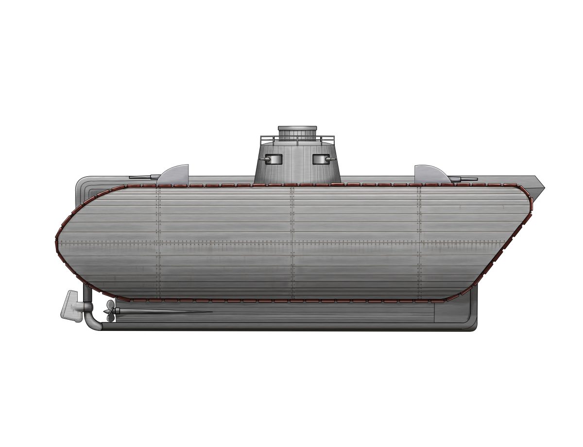
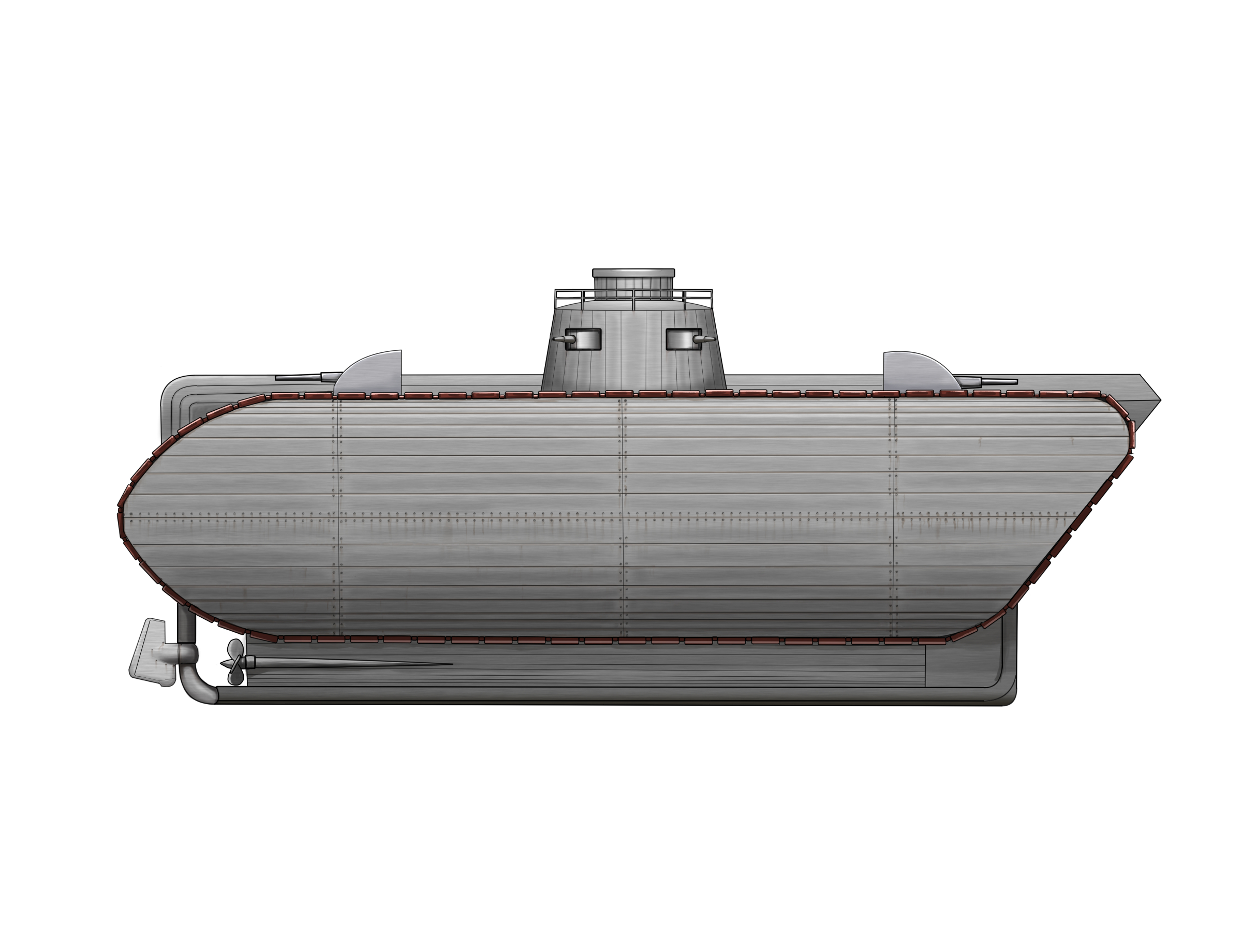
The basic layout of the Naval Tank was in three sections, rather akin to a hot dog. The sausage itself was the ‘ship’ part of the vehicle, and the bun on either side was the land ‘tank’ part. The central section was made with vertical sides and a rounded top and bottom. The bottom formed the keel of the tank which, when in the water, would provide stability and, whilst on land, form the bottom of the hull of the vehicle.
In this central portion lay the powerplant which, according to Biemmi’s drawing, was located centrally, directly under the conning tower. Fore and aft of the powerplant were a series of vertical hydraulic cylinders which were connected at the base to the floor of this central section and were connected the central supporting framework for the whole vehicle. The rear of this section was rounded off, whilst the front was sharply angled to a point projecting just beyond the rearmost point of the tracks.

Source: Radio – Scienza e Vita, October 1930.
On either side of the ‘dog’ was the ‘bun’, consisting of a pair of mirror image track units. With an all-round track (track running around the outside of the unit), each one was constructed from a large lattice framework, with the top and bottom of the track running parallel to each other. The rear was angled sharply upwards at about 45º, whilst the front of the track units was rounded off symmetrically above and below. The sides of the track units were not vertical but were convex, projecting out from the front producing a rounded side profile.
On top of all of this was a pair of gun batteries, with one at each end of the central section, forming a line of three guns on each side. Between those and in the center of the hull was an oval frustoconical conning tower.

Source: Radio – Scienza e Vita, October 1930.
Firepower
Whilst Biemmi drew several guns, he made no comments about the sort of suggested armament for such a vehicle. With the goal of supporting troops as they came ashore, a variety of weapons, from machine guns up to medium caliber artillery guns, may have been thought of. However, without mentioning or suggesting suitable choices, it can only be speculated what he was considering for armament.
The arrangement, however, is well shown. Two banks of guns, with one fore and the other aft, formed into what appears to be a traverse-fixed firing mounting, each with 3 guns. The mounting is shown with a curved face and vertical rear. Slots in this were provided to allow for high elevation. The vehicle would have to point in the right direction for weapons arranged like this to have any value, and regardless of which way it faced, the other battery would be facing in the opposite direction and be of little of no use. The fixed conning tower was also armed. The tower itself was oval and fixed to the hull, with the sides sloping upwards to a shallowly domed roof and surrounded by what, from the drawing, appears to be a small safety rail. In the center of that was a cylindrical structure which could have been an idea for a turret, but which is neither shown armed nor obviously rotatable. Instead, the only armament shown in the tower are four weapons mounted around the outer circumference, arranged equidistantly apart, so that two were on each side, meaning whichever way the vehicle approached a target or was approached by another vessel, at least two of the guns would be able to face it. Once more, no specified armament was suggested.
Mobility
Propulsion for the Naval Tank was by means of conventional internal combustion engines. Power from these engines would be delivered to the tracks when operating on land and to the pair of propellers when in the water for movement. Whilst it may appear that the three sections of the machine moved relative to each other, this is not the case. It was only the hull/keel of the middle section which moved, pushed down into a position below the bottom of the tracks on either side of it when being propelled in the water.

Source: Radio – Scienza e Vita, October 1930.
When the vehicle operated in shallow water or on land, the hydraulic rams lifted the hull/keel part of the central section back into place. Thus, the vehicle would, in theory, be able to drive from land into the water, become buoyant and then push down the keel to begin to travel as a ship. On the converse, as the vessel approached land, the keel would be raised, allowing the tracks to contact the ground and the vehicle to then drive ashore under its own power. All of this movement could be done without affecting the top of the vehicle, which could interrupt either visibility or the ability to deliver fire in support of the troops.
On Land
Whilst operating on land, the hull of the central section of the Naval Tank would be in the ‘up’ position, allowing the track units to have contact with the ground. The top speed would be just 10 km/h, which was not fast by any means, but would have been more than sufficient to support unmounted infantry, and was essentially just the same sort of speed of a tank from WW1.

Source: Radio – Scienza e Vita, October 1930.
In the Sea
At sea, with the hull in the ‘down’ position, the keel of the vehicle was down, providing stability, and the top of the track sections was out of the water. They were, however, still submerged to more than half their depth, and this provides a necessary width to the vessel to provide stability, albeit, at the cost of some streamlining.
It was, afterall, not a true ship anyway, so this is not such a problem, and yet, even so, Biemmi proposed a top speed in the water of 15 km/h from the propellers.

Source: Radio – Scienza e Vita, October 1930.
Armor
Whilst at sea, the Naval Tank would float with only the tops of the tracks and central hull section exposed above the water line. The deck of the central section, carrying the primary firepower and the conning tower, would be visible, but were of a low profile and able to return fire just as easily at sea (notwithstanding the movement of the water) as it would on land. Certainly, those immersed parts would be well protected from enemy observations and fire, as they are below the water line.
The sides over the track units were convex, made from 8 large armored panels. Presumably, the tank was to be made from steel to provide some modicum of protection, although Biemmi neither provided the material nor any idea of what sort of protection he was thinking of. For all of the moving parts of the track and suspension however, he does provide information, namely proposing making these areas out of stainless steel to prevent corrosion.
Conclusion
Biemmi’s design was really more of a concept of perhaps how such a vehicle might look and work, and he wrote that the size could be varied depending where such a vehicle might be intended to operate. These could be small vehicles for intercoastal work offloaded from a ‘mother’ ship, and perhaps larger vehicles for taking a landing all the way across the sea under its own power all or some of the way, and using this larger version to show all of the features in the best detail.
Biemmi was undoubtedly correct in his goal to provide some thought on the problems of amphibious tanks or landing tanks from the sea. He even considered some of the problems of corrosion of components too and how to provide both propulsion and stability. However, where this design seriously falls short is undoubtedly within the ideas of armament. The conning tower appears to be fixed in place, meaning that the weaponry has to be deployed around it to provide the firepower in different directions. Allowing this tower to rotate as a turret would at least have allowed the firepower to be concentrated in one place and reduced the number of men needed to operate such a vehicle. Each gun required an operator and all of the problems of trying to command and control a large crew, of whom perhaps half were facing their weapons in the wrong direction.
Indeed, given the large Italian Navy (Regia Marina) at the time, it is somewhat surprising that the vehicle was simply not provided even with a naval style of central turret or any turret at all. Replacing the conning tower with a turret and abandoning the fixed hull guns would have provided a vehicle needing fewer crew and fewer guns and able to focus all of its firepower in one point as well as being easier to control.
Biemmi also missed one other potential feature – a large hatch or door of some description. The possibility of internal space within the central part of the machine could easily have been repurposed in some manner to create some space for landing troops.
Despite the good intentions of Biemmi to try and provoke some thought on a naval tank for Italy, it came to nothing. Ten years later, when Italy entered WW2 on the side of Germany, it still had no such vehicle and was still dominated by vehicles such as the CV.3 Series light tank, with the heaviest tank which might be involved in such an attack being the M.11/39 medium tank. Neither of these vehicles would be suitable for the purpose Biemmi envisaged.

Source: Popular Science Magazine May 1938
Specifications Biemmi’s Naval Tank |
|
|---|---|
| Crew | unknown |
| Engine | Internal Combustion type |
| Speed | 10 km/h (land), 15 km/h (water) |
| Armament | 6 fixed traverse guns in two batteries on the hull. Four guns in fixed conning tower. |
Sources
Popular Science Magazine, May 1935
Radio – Scienza e Vita, year II – N. 13 – 1-15 October 1930.
2 replies on “Biemmi Naval Tank”
Hello, I love this article! It is truly facinating! But I do have a question: in the “Specifications Biemmi’s Naval Tank”, in the armament, there is written “Four gins in fixed conning tower”. What does “gins” mean? Or is it suppose to be “guns”? Like all the work done for this website by the way!
Yes, it is just a typo. We will fix it.
Thanks
Gareth (TE Manager)