 France (1914-1920)
Prototype – 2 Built
Probably the most unlikely looking of all tank designs is the famous Boirault machine or, to give it its full name, the Fortin Automobile ‘la Machine Boirault écrase barbelé’ (Eng: The Barbed Wire Crushing Boirault Machine). Usually used as an example of bad design or for mockery, these machines were an ingenious and inventive means of crossing trenches and broken ground and were not the product of some random inventor. These designs came from the highly respected and very well experienced French Engineer Louis Boirault. Boirault was an undenied expert in railways in his position in the state rail system. Specifically, he was an expert in railway couplings, and between 1900 and the 1920s, having had amassed over 120 patents to his name, mostly for railway connected matters.

When, in August 1914, Germany declared war on France, few could have envisaged the mostly static grinding butchery that the war would become. Most armies were grossly unprepared for the mass slaughter brought about by the industrialization of Western Europe, with machine guns and artillery becoming the predominant weapons of war rather than the rifle or lance. It was not long, however, before the armies settled into lines of defense with each side unable to inflict a decisive breakthrough and defeat the other. By the end of 1914, with casualties mounting rapidly (over 300,000 men by the end of the year,) inventive minds across Europe were awaiting a breakthrough, so it is no surprise that a man such as Boirault should turn his engineering prowess to the difficult question of how to take the war to the enemy across open ground cut with trenches, guarded by belts of barbed wire, and covered by machine gunfire. An armored machine was the inevitable outcome, but wheeled vehicles could not cross such ground and, in 1914, there were few tracked machines available in France on which to base such a vehicle. Whilst the French designs eventually ended up using the Holt tractor chassis (a chassis rejected early in 1915 by the British) there was, with the war ground to a halt, in 1915 a period of experimentation looking at methods of attack by machine. Monsieur Boirault’s idea would stand out amongst many others as the most original.
Origins December 1914 to February 1915
In December 1914, Louis Boirault and his company (the Boirault Company) started considering the question of crossing no man’s land (the area between the front lines of the opposing armies) and proposed a solution to the French War Ministry. With few other options, the War Ministry authorized production on 3rd January 1915, and under the eye of a commission to supervise the invention led by Paul Painleve (Minister for Inventions), construction began. By February 1915, his considerable experience with railways led to his design ideas being presented to the French military, which were evaluated along with various other, often odd ideas, offering solutions to the same problem.

An Inventive Design
Instead of wheels, he envisaged tracks. Not the sort of tracks used in some agricultural vehicles of the age, but much more akin to what he knew: train tracks. Obviously, you cannot lay train tracks for a train to attack the enemy, so the answer is to simply bring them with you. With two parallel rails attached horizontally by 4 steel girders, this machine used 6 sets of these frames to carry the machine. The ‘rail’ parts and the ‘sleeper’ parts spanning between them across the frames would carry the load of the vehicle on the soft ground and as the machine advanced they would simply be picked up behind and carried back over the top of the vehicle to be laid in front once more. This is exactly the same principle as other track layers but the single-track nature and sheer size of the tracks in question make it look more unusual than it actually is as an idea.


Each frame was simple and rugged and obviated the problems found with other tracked vehicles of the time. There was no track sag (where the tracks drop away from the body of the vehicle or running gear), there was no lateral slippage (tracks slipping off the wheels sideways), and, most importantly, the six frames required just 12 pins to attach them together, which reduced the chances of a pin failing because they could be made very substantial, like a railway car coupling. These three problems that plagued early tracked vehicles were ‘solved’ so to speak, in one simple move, but the price of this solution was also, eventually, to be its greatest failing.


The machine inside this 6-frame-track run was an unusual rectangular based pyramid with the edges of the pyramid constructed from the same type of heavy steel girders used in the frame sections. Where these pieces met the frame at the bottom (2 contact points per side) and at the top of the triangular sides (one per side) there was a heavy steel roller along with a large square section ‘doughnut’ forming a path through which the frame sections would run. This was a very rigid and robust system for which there would be no movement at all of the track. Effectively, it was as if a train’s wheel was being held firmly onto a track and taking all of the weight. Within this pyramidical structure, at the heart of the machine, lay the Aster petrol engine. This engine drove the tracks by means of steel drive chains but was underpowered for the task and capable of propelling the machine at just 1.6 km/h (1 mph). It is worth noting that at least one contemporary source states that the 80 hp petrol engine used came from the Filtz agricultural tractor.
Under this engine, and within the body of the machine, a crew would have to be accommodated somewhere, along with fuel, and, at some point, some kind of offensive weaponry. The drive was at the top of the machine. Whilst this had the huge advantage that the drive could not get clogged with wire or mud, it also meant that the crew sat underneath all of this, making it harder to see, and raised the center of gravity for the machine. The bottom of the pyramidical vehicle can be seen in photographs to have a curved bow and stern section and would slide along the frame on its wheels crushing down any obstacles such as barbed wire staves in its way.

Problems
The design, despite being functional and able to move under its own power, was unsuitable for war. The French military authorities found the machine to be robust and ingenious but the faults were obvious. Firstly, it was huge, and perhaps it was because the size and slowness of it some officers christened this ‘Appareil Boirault’ machine with the tongue-in-cheek moniker of ‘Diplodocus militaris’ – a military dinosaur (the Diplodocus was a large long-necked herbivore living in the late Jurassic period about 150 million years ago). Measuring 8 meters long, it was still narrow enough as a machine (just 3 meters wide) to be transported by rail, but this would have to be done partially disassembled because, at 4 meters high, it would not clear any bridges. The height was also a considerable problem, it would be impossible to hide from enemy observation and very vulnerable to enemy fire. With the engine at the top, it would become crippled quickly, although the lack of conventional track plates would at least render these huge frames safe from damage by concentrated machine-gun fire on them. At just 1.6 km/h (1 mph), the machine would be unable to evade fire, and being easily targeted would have to carry a large weight of armor which would make it even less mobile. Clearly, this was all impractical even though these frames enabled it to cross trenches up to 3-4 meters wide. The greatest fault though was steering. With just a single track and no means of altering power to one side or another or hydraulic adjustment on the machine, the machine would only be able to move in a straight line. Whatever direction it was pointed in when it set off would be its direction, forwards or backward, making it even easier to hit as a target and also rendering it likely to be thrown off course by undulations in the ground.
If that happened, the two-man crew (presumably a driver, and a commander who would have to operate whatever weapon might have been mounted eventually), would have to exit the vehicle and laboriously use jacks to lift one side of the vehicle from the ground to bring it back on course: a suicidal endeavor in the middle of no man’s land.
According to the historian Alain Gougard, these faults were published in an official report on the subject on 17th May, and consequently, on 10th June 1915, this first machine was abandoned. The historian Francois Vauvallier, however, gives the dates of the test not in February 1915, but on 10th April 1915, although it is possible that testing actually spanned that period. He also provides the date of abandonment of the design as 21st June 1915, not the 10th, but either way, by the end of June 1915, it was officially abandoned.

A New Hope – A Second Trial
All was not lost for Monsieur Boirault though. This was still the middle of 1915 and the French Army still did not have an effective tank. In context, the British had yet to perfect the all-steel tank track, so it can be understood that this was still very early on in the development of tank warfare. Boirault was stubborn in his insistence as to the viability of his design and he had been correct that the design worked. The resulting efforts by him pressing his case meant that the French Government created a new commission to oversee his work and authorized him to produce an improved version of this machine. Howard states that this improved machine was scheduled for trails to take place in November 1915, but this second phase is not mentioned at all by Vauvallier.

This second trial, organized on 4th November 1915 and taking place on the 13th, showed once more that the machine moved. This time it was laden with 9 tonnes of ballast to simulate arms and armor which would be fitted and albeit still very slowly, merrily plowed through a barbed-wire entanglement 8 meters deep and over a two-meter wide trench.
The primary modification to the machine appears to have been in the steering. Previously, a single large external jack was used, but this November trial demonstrated an internal system of smaller jacks operated from inside the machine. It is not clear when these were fitted, but given the criticisms of the machine from the spring trials and the lack of obvious visual changes, the addition of these smaller internal jacks is a logical assumption. Either way, turning was very slow, had to be done from a halt and was limited to a maximum of 45 degrees.
The modifications proved insufficient to overcome the inherent problems of the design and once more the machine was rejected.
Reborn
With the first machine having proved his theory at least technical sound, if not very practical, Boirault used his company and experience to produce a second vehicle. This new machine was substantially different from the first machine incorporating the same ‘over the top’ single track principle but substantially smaller and with a much more compact track run. Vauvallier states that this machine was already underway in either design or construction by the time of the November 1915 trials of the first machine.
A New Design
Tracks
The essential principle of traction remained the same. A track run going completely around the machine made from six steel frames with the engine and fighting compartment located enclosed within the track run. Each frame was more compact this time, no longer the huge open rectangular frame of the first machine with four horizontal spars. This time the frames were square and made from four steel girders braced together at each corner by a triangular plate and with two rectangular ‘feet’ projecting from each side providing for additional grip on the ground. On the inside of the frame, running vertically through it, was a single steel girder connecting each of the center couplings together and connected from that was a further brace to each corner of the frame. Those four external girders, together with the triangular corner bracing, provided the ground contact area and also left a large octagonal space on the outside of the frame. Each frame segment was coupled to the preceding and following frame by a heavy steel pin in the connecting corners and also by a flexible coupling in the center, providing a very solid means of connecting each ‘link’ in this giant-sized track to each other. This massive type of track construction rendered the track impervious to damage from machine-gun fire and also providing protection for the cabin within, but also a robust system unlikely to be damaged by any obstacles it might contact on the ground. These massive frame tracks were so substantial in fact that it is hard to imagine the damage to them being caused by anything short of a direct hit by a field gun or shell.

An important change to the connections in this track system though was that the connections at the corners and the coupling had a small degree of lateral flexibility. Rather like the railcar coupling Boirault was so familiar with (and an expert in the design of), each frame could twist slightly against the other providing the steering movement for the vehicle. The wholly useless jacking system of the first machine was totally abandoned in favor of this design which not only ensured the crew could stay enclosed in armor, but that steering could also be effected on the move. What is unclear is exactly how this ‘flexing’ of a frame was to be carried, but as the original jacks on the floor of Machine One were hydraulic, it is a logical extraction that these jacks moved to either the rear, front or roof of the machine could be used to push on one side of a frame as it moved over it, in order to effect the movement. This system certainly worked but provided for a marginal turning movement and when this machine was later tested the radius of a turn to be 100 m.
Cabin
The old machine used a pyramid-shaped cabin with the curved bottom section holding the ‘cab’, although it was open to the elements and with the engine and gearing above them. Essentially, this setup with engine-over-crew was retained on the second machine but totally gone was the tall pyramid. Instead, a new, rhomboidal shaped cabin was built with a pointed bow and stern. Constructed from heavy armor plate riveted to a steel frame, the gearing was still at the top, along with the drive chains, but the engine had been moved lower down into the rear of the machine.

This had the advantage of substantially lowering both the profile of the tank but also its center of gravity so it was less prone to toppling sideways. Access to this machine was by means of a large rectangular door on each side which had a curved top opening backward. In each door, a portal was fitted into which presumably a machine gun could be mounted, although no armament was specified.

One photograph from trials of this machine seems to indicate a weapon mounting on the nose section of the machine which could be interpreted as the sort of weapon like a 75mm cannon required for breaking up an enemy position and later used on the Schneider CA-1, although this is speculation.

Trials and Tribulations
The spring trials of 1915 showed that the first machine had significant problems with height, speed and steering. Amendments made by the end of the year led to further trials of it in November with amendments to the steering system. These had still proven inadequate and that machine was abandoned. The principles employed though remained, and the second machine had a new steering system using the same type of ‘frame track’. When this second machine was finished, it was subjected to trials by the Army on 17th August 1916 at Souain-Perthes-les-Hurlus, in North-Eastern France. This was probably also the site of the 1915 trials of the first vehicle.
Here, despite the obvious improvements to the machine and its heavy armor and construction combined with the ability to cross a trench 1.8 meters wide, the low speed (under 2 km/h) meant that it failed to impress the Army. General Henri Gouraud (4th Army) however, was more sanguine on the matter despite the obvious problems. He was very impressed by the ingenuity of the design and the robust nature of the design. Narrower than the first machine it was still able to plow effectively through belts of barbed wire creating an avenue for any infantry to follow which was more than 2 meters wide – something which was in critical demand at the time but which was now also solved by new designs using a new robust pair of tracks.


Postscript to the War
In a report dated 20th August 1916, Gen. Gouraud indicated he would have preferred further trials of an improved machine but these, sadly, were not to pass, and the design was abandoned by the military in favor of new tank designs which were becoming available to them. This was not, however, as thought by many historians, to be the end of the Boirault vehicles or Monsieur Boirault’s interest in this type of traction technology.
After the war was over, he continued his development with the submission of a patent in France (number FR513156) for ‘Appareil roulant pouvant etre employe comme pont automobile’ (Rolling apparatus that can be used as a motor bridge) on 1st April 1919. The patent was granted on 28th October 1920 and published the following February.

The patent was nothing short of optimistic, envisaging hundreds of such frame-machines like his 1915 design with the pyramidical center acting together to form a type of rail bridge would be employed to replace missing bridges, create entirely new bridges, and even off-load full-size steam locomotives from a ship. Each frame-machine could use multiple vehicles within them to literally create a mobile moving bridge although quite how these were to actually function outside of a paper design is unclear but given that his first machine can be accepted as a ‘tank’ in some aspects, then this 1919 patent can also be accepted, by extension, as probably the most unusual tracked bridging vehicle imagined. This design was never committed to construction and it remained entirely on paper as a patent, perhaps simply just to stop someone else taking the ideas on which he had worked so hard through the difficult years of 1915 and 1916. One final note from the design is shown in Figure 8. Figure 8 shows a 12-frame machine carrying what appears to be a very heavy field piece of artillery. This enormous single-engine carrying this gun was representing a potential single engine of war or transportation replacing a series of frames using smaller engines within them. It is hard to quantify whether this additional Boirault design is a tank, a bridge, a transporter or something of all three, but certainly, the vision and ingenuity of Monsieur Boirault seemed boundless with this idea.

Conclusion
The Boirault tanks were undoubtedly the most unusual tanks built and tested during the First World War and came around at a time when the technology relating to AFVs was in its infancy. The problems faced by the first machine were mostly overcome, save for speed and turning, but given the enormous progress between the two designs, it is reasonable to imagine that, given more time, this machine could genuinely have been put into production to create breaches in the enemy wire. It is perhaps sad from an engineering viewpoint that he did not continue his unique style of vehicles as tanks or attempt, post-war, an even more adventurously sized vehicle.
What is clear from his work, however, is that these machines worked. They achieved everything he had expected of them and at the time they were designed were the only machines available to the French capable of crushing the wire in no-man’s land and crossing trenches. They should not be looked upon as a failed design or something ridiculous but as a triumph of the power of engineering skills married to the imagination to come up with an innovative solution to a problem killing tens of thousands of men. Monsieur Boirault was a pioneer who helped to spur the military in France to produce tanks for the war effort. Regardless of the fact that his machines were never used in combat, the path to the design of a workable tank was a difficult one for all nations. A difficult journey in which he played his part, and should, therefore, be recognized as such, a visionary, a patriot, and engineering visionary.
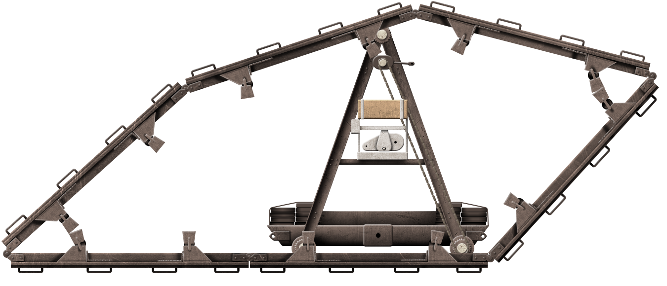
Illustration of the Fortin Automobile ‘la Machine Boirault écrase barbelé’ (Eng: The Barbed Wire Crushing Boirault Machine) produced by Yuvnashva Sharma, funded by our Patreon campaign.
Specifications (Prototype No. 1) |
|
| Dimensions (L-W-H) | 8 x 4 x 3 meters |
| Total weight, battle-ready | 30 tonnes (+9 tonnes ballast later) |
| Crew | ~2 (Commander, Gunners) |
| Propulsion | 80hp Aster petrol engine from a Filtz agricultural tractor (petrol) |
| Speed | 1.6 km/h |
Specifications (Prototype No. 2) |
|
| Dimensions (L-W-H) | 6-8 x ~3 x ~ 2-3 meters |
| Total weight, battle-ready | 30-40 tonnes |
| Crew | ~4 (Driver, Commander, Gunners x 2) |
| Speed | 2 km/h |
| Armament | est. two machine guns and one cannon |
| Armor | ~25mm |
Sources
French Patent FR513156(A) Appareil roulant pouvant etre employe comme pont automobile, filed 1st April 1919. Accepted 28th October 1920. Published 9th February 1920
Gougaud, A. (1987). L’aube de la Gloire – Les Autos-Milirailleruses et les Chars Francais pendant la Grande Guerre. Societe Ocebur
Granier, V. (1919). Les etapes successives de l’arme victorieuse: Le tank. La Science et la Vie No.44
Vauvallier, F. (2014). The Encyclopedia of French Tanks and Armoured Fighting Vehicles: 1914-1940. Histoire and Collections.
Zaloga, S. (2010). French Tanks of World War 1. Osprey Publications
5 replies on “Boirault Machine”
Awesome, Great job on such a rare beautiful beast!!!
Hey, hi Tim @Landship.info !
Thanks, and have a nice Xmas/new year !
Nice work,
p. s. Merry Xmas ?
https://www.facebook.com/groups/217019968450028/posts/2070804869738186/
!!!
Important addition. There is a video of Boirault machine (second prototype) being tested as mobile bridge for “Saint Chamond” tank as late as 1918:
https://images.cnrs.fr/en/video/6673
Apparently the armor was removed, and machine was equipped with additional wooden beams and tail ramp. The idea, if I understood correctly, was that machine would be used as mobile bridge to cross moats and high walls.