 United States of America (1898)
Self-Propelled Gun – None Built
The second half of the 19th century was a period of rapidly increasing industrialization and the development of better and better machines, refined by science and war. Old tactics and concepts of warfare had to evolve and keep up as new devices, like a reliable modern machine gun, were quickly being evaluated and adopted by major armies whilst, simultaneously, civilian developments, like the first motor cars, were replacing horse-drawn transport on the roads.
With a crude layout, Henry Osborn submitted a patent application in 1898 for what is one of the first known mechanically propelled armored fighting vehicles. Crude by today’s standards, the vehicle embodied many elements later taken for granted on a vehicle as well as a concept of how to actually deploy the vehicle in combat – something commonly lacking many of the often outlandish designs conceptualized in a patent before and since.
The Man
Henry Porter Osborn of New York, NY, USA filed this patent for what he described as a “new and useful Shield-Protected Automobile Gun Carriage” on 21st May 1898. He qualified as a dentist in 1889 and was living in New York, practicing his craft out of number 10 East 48th Street. He is believed to have died in 1918 but, other than that, there is very little information available about this man. The only other known official record for him is another patent application he filed two years before his gun carriage. That patent, for the construction of a brush, took 10 years to be granted which, if not a record, was still an extraordinary amount of time.
The Vehicle
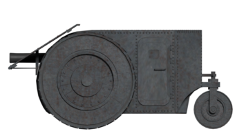
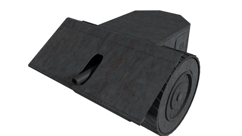
Based around a simple trio of wheels, the carriage is a simple affair. Two large diameter and wide wheels are at the front with a third, smaller diameter wheel at the rear to provide steering. Between these three wheels is a large rectangular platform on which a crew could operate and which narrowed towards the back where the platform met the steering wheel. In front of this platform was a large angular shield in the shape of a ‘V’ on its side, reaching almost as high as the top of the front wheels and through which a large firing loophole was provided for a forward-facing large calibre gun. With the shield in this position, it would provide complete protection for the men operating the vehicle. The vehicle was outlined in two forms. The first was a simple open-topped design with a single large cannon facing forwards and the second used a contained shelter for the men within a complete enclosure of armor.

This second form was substantially wider than the first and carried up to 8 large caliber guns in the same manner as the first outline. The primary difference between the two schemes was the size and power, as the second vehicle clearly shows a space alongside the wheels in the front for motors. The use of 8 guns in the wider form of the vehicle was, however, merely indicating that the platform could be made any width as required to provide guns facing forwards. The wheels and body of the vehicle were to be made from the “best shot-proof steel known to the arts”. Thus, even in the initial roofless form, the wheels themselves provide protection for enemy fire for the men operating the carriage.
Further protection could be gained by parking the front of the vehicle against a wall, rampart, or earthen embankment to cover the lower half from return fire by the enemy.

Propulsion
Power for Osborn’s Gun Carriage was envisaged to be provided by electric motors or steam or “any other form of motor”, including petroleum or kerosene motors or even just animal-drawn. Were it to be animal-powered, the horses, mules, or even oxen would be connected to the rear of the vehicle to provide ‘push’ rather than to tow it behind in the manner of a cart. The engines were located on each side of the vehicle, just on the inside of each of the large front wheels. These wheels were to be hollow to save weight and space but wide enough to spread the load from the vehicle on the ground.

During road travel when not in combat, Osborn’s carriage could be connected to another such carriage by removing the third wheel from the back of each to create a four-wheeled vehicle. Obviously, this removed the steering wheels from the vehicle but this did not matter for it was to become a towed carriage on a railway rather than propel itself when so connected. All that remained for it to move by rail was the addition of flanges to the wheels to ensure it stayed on the rails during transport. Likewise, if it was using electric motors, it could simply deploy a trolley-car type electric connection from above it to draw power from overhead lines. One factor not considered by Osborn however, was that this method could only be used by a vehicle the width of a US railroad or trolley-car line. For reference, this meant a track width of perhaps as little as 3’ 6” (1,067 mm) for a trolley car up to 4’ 8 ½” (1,435 mm) for the US standard rail gauge.
Electrical propulsion was clearly Osborn’s preferred means, as he not only described a system for powering it from an overhead trolley-car line but also that the space enclosed by these large hollow wheels could also be used for large batteries on each side. Storing charge, these batteries would then, in theory, be able to propel the carriage to its destination.
Crew
At a minimum, the vehicle would need one man to control the steering at the back and possibly the engines/motors as well. Unless this single man was to park and then operate a single gun alone, it is logical to assume a normal gun crew for each of the cannons, so a crew of possibly 5 men or so for the one-gun form of the carriage and thereafter an additional 2-4 men per gun. Following the rudimentary drawing, it would appear that access was to be gained from the rear although other doors are possible.

Conclusion
This is a very early concept for a mobile gun battery. Considering the technology available to him in 1898, Osborn came up with a clever concept for using these open-backed large diameter wheels for both protection from enemy fire and also for covering the engines or motors and batteries on each side.
At a time when field guns were almost entirely still drawn singly and by animals, Osborn even understood the power of additional mobility by using rail or trolley lines to move his guns as well as how it should be deployed to present a small target to the enemy.

Specifications Osborn’s Electric Gun Carriage |
|
| Crew | 1+ gun crews |
| Propulsion | Electric or steam (or any other form of motor including petroleum and kerosene), or drawn by animals. |
| Armament | 1 or more large calibre guns facing forwards. |
| Armor | “best shot-proof steel” |
| Total production | None built |
Sources
US Patent US698049 Gun Carriage, filed 21st May 1898, granted 22nd April 1902
US Patent US 832805 Brush Construction, filed 6th August 1896, granted 9th October 1906
Westfield New Jersey History https://www.westfieldnjhistory.com/greavesfiles/fam05227.htm
Polk’s Dental Register and Directory of the United States and Canada. 11th Edition 1914-1915. R. L. Polk. and Co. Publishers, NY, USA