 United States of America (1916)
Self-Propelled Gun – None Built
World War One brought about numerous technical innovations to break the stalemate of static warfare which had rapidly become the defining characteristic of the war. Then, as now, it was artillery that was the key to defeating enemy defenses. The need to move large caliber guns to the front was fundamental to any army trying to achieve a breakthrough. Although the USA was not at war in 1916, this was a conflict watched keenly around the world as the fighting developed and was widely reported. Stanley Glonin̈ger Miller from St. Paul, Minnesota, a manufacturer by trade, Dorcy Olen DeWitt, also from St. Paul, who worked for the Crex Carpet Company as a machinist, and Myron Wilber Robinson, from New York City and also a manufacturer, submitted a patent application on 21st February 1916, ostensibly as an ‘Improvement in Belt-rail tractors’ for military purposes. What they actually designed was one of the world’s first tracked self-propelled guns.
The information for the design is held squarely within patent applications filed in the UK, Canada, and United States by those three men. These three men knew each other, as they all worked at the Crex Carpet Company. DeWitt was a machinist and employee, Miller was a Vice President, and Robinson was the President of the firm.
The firm itself bears some scrutiny, as it took harvested and dried wiregrass and wove it into twine and later into wicker products. The company had previously been the American Grass Twine Company which, in 1903, was rebranded as ‘Crex’, taken from the Latin name for the grass used, Carex Stricta. Woven into mats and carpets and wicker products, Crex was a profitable market-leading company for a short time and was even listed on the New York Stock Exchange in 1908.
Large factory floor space was needed to turn this dried tough grass into a workable material and machine looms would run, turning it into matting and carpet and eventually into wicker. By the time of the outbreak of the World War, the wicker industry from grass was waning. It was being replaced with wicker made from paper which had been invented in 1904 and, being cheaper to produce and easier to work with, rapidly ate away at Crex to the point where, in 1917, the firm had all but ceased to exist. Wicker was gone from its products and its decline only ended in 1935, when it finally went bankrupt.
This is relevant to the design from Miller et al. as, at the time it was drawn up, these men, who knew a thing or two about machinery and engineering processes, were looking for a new and profitable enterprise to which they could turn their energies.
Quite what inspired the design they came up with is not clear. It could well be a function of seeing tracked harvesting machines at work collecting their raw grass product. After all, this was the inspiration for Robert Macfie to look at Holt tractors in the UK in 1915 using his sugar plantation experiences.
With a war raging in Europe, it cannot have been made in isolation and, yet, the time of application for the patent is somewhat remarkable. January and February 1916, just months after the British had ordered a Top Secret new weapon into production – the tank. There was absolutely no way in which these men could possibly have known of that development so this was an advance made in isolation, a case of convergent evolution where the same solution comes about as a result of the same pressures.
The patents in question were filed in the UK on 18th February 1916, but the Canadian filing for it was even earlier, on 20th January 1916. All this was at a time when the United States was not even engaged in World War One, but in which these men could not have been unaware of one of the key problems encountered – how to get large artillery guns and other material to the front.
Mobility
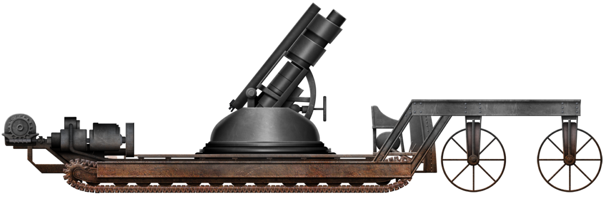
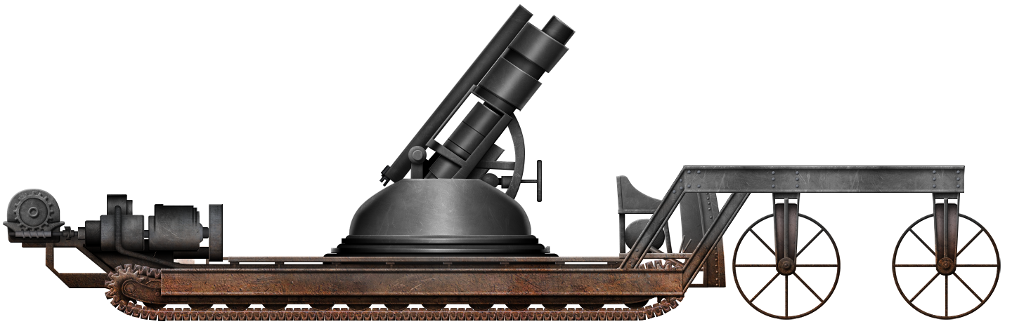
Traveling on what they called a ‘belt-rail’, which would be recognized today as a caterpillar-type track, the machine was to be able to traverse irregularities and undulations of the ground, soft or broken, and small obstacles to get where it needed to go. One of the key features in doing so was to keep the center of gravity for the vehicle as low as possible to reduce the chance of it overturning.
Layout
The vehicle was divided into two sections. The first took the form of the mobile tractor frame mounted on tracks and which was fitted with the engine and gearing. The second part of the vehicle was a structural framework that pivoted to the tractor frame. This part was fitted with guiding wheels that controlled the steering of the entire vehicle.
The primary frame was rectangular in shape and made from two longitudinal steel beams. Slung perpendicular between those two beams was a series of bracing beams to which the tractor units were connected.
Above the track units was a low slung platform on which the load of the vehicle sat.


Automotive
In the patent drawings, three sets of tracks are used, but the description is clear that any number of track units could be fitted to a framework in this way. Power to those tracks was delivered via a very simple worm gear from the output shaft. This worm gear drove a large tooth gear that powered the tracks. The power for that worm gear came from an internal combustion-type engine.

The tracks were formed from interconnected metal links with a V-shaped grouser and were considered sufficiently different from existing tracks to warrant another patent application, submitted on the same day like that for the tractor. UK patent GB104135 for the tracks shows these interconnected thin one-piece links connected together by steel pins and using a built-in track guide in the center to hold the hold to the wheels preventing lateral movement. This is notable as, in 1916, the form of track being used was a simpler plate attached to a shoe, with the shoes being connected together and dragged around the vehicle by the drive sprocket. Early tanks, such as the British Mark I or French FT, used this shoe method. Those tanks also had separate plates which were fitted close together but did not intermesh. The design from Miller et al. wanted the edges of each link to intermesh with the preceding and following links. For a design in February 1916, seven months before tanks were even first used and entered the public imagination, this was an advanced system of track for a vehicle. It is worth noting that, although the British patent for this link was filed in February, the US patent for the tracks was filed on 10th January 1916.


Vertical movement of the front of the vehicle was controlled by hydraulic cylinders which served to prevent lateral movement but permit vertical movement whilst ensuring that the wheels stayed pressed onto the ground.
The similarity of this idea to the British use of wheels on the back of the Mark I tank in 1916 is very striking here. The Mark I used a system of springs to push the wheels down for the dual purpose of steering and to help raise the nose of the tank to climb obstacles. There is no mention of obstacle climbing assistance for the Miller et al. design, but the use of a system to keep the steering wheels pressed into the ground is very much the same.
On the Mark I tank, these were found to be superfluous and really a bit of a hangover from the original ideas of 1915, slaving tractors back to back, and were quickly abandoned. It is not necessarily the same situation with the Miller et al. design, as the wheels are at the front, substantially wider, and also more numerous. However, should Miller et al. have selected a second steerable track unit to be mounted in place of those wheels or a mechanism to vary drive to the tracks to provide the steering, this would have been a better steering solution for the vehicle.
Armament
No armament is specifically mentioned in the patent for the vehicle, other than to say there was sufficient space for “a gun”. The drawing, however, clearly shows a large-caliber mortar or howitzer on a mounting which appears to be shown capable of rotating on its base. Mounting a gun in this manner would have been a significant advantage for an Army of the age as, in 1916, there were no heavy guns mounted on tracked self-propelled carriages. Heavy guns, instead, had to be hauled around on old-fashioned wheeled limbers by horses, or trucks. This was a slow process which meant they were hard to move and slow to get into position on broken ground. They would then have to be set up in place to fire and could only fire from that position. If the gun had to be moved even a relatively short distance, it would have to be limbered back up, moved, dismounted, and set up all over again. This situation was even worse for large-caliber guns, which often had to be shipped in multiple pieces due to the size and weight of the elements of the gun and carriage.
With a self-propelled chassis, this was not the case and several armies, notably the Italians, placed field guns on heavy trucks to create a mobile artillery force. Whilst that system could indeed move guns around fairly quickly, what they could not do was move very well off-road and the maximum load carried was just 5 tonnes or so – limited by the strength of the truck frame and tires.
By using tracks in this design, Miller et al. would be able not only to move around on or off-road more easily but also carry a far larger (and heavier gun) if they wished to. A gun such as the British Ordnance BL 9.2” howitzer of the era weighed over 5 tonnes just for the gun alone, without including ammunition. A platform like this would have been able to mount such a gun and ammunition and the men to crew it and move it around. It might not have been fast but it would be a far quicker alternative method of moving the gun used to that point.

Even if a gun was not being carried, this platform system would have been adequate for men, supplies, ammunition to be carried relatively simply, although it must be borne in mind that there is no armor and no protection from the elements for the men or load being carried.
Conclusion
The design from Miller, DeWitt, and Robinson was never built, it received no orders and the hopes of these men to profit from this design turned to nothing. When they submitted their design, Great Britain had already been at war since 1914 and, in 1917, the USA also joined in. Spring 1916, when they submitted this design, coincided with the British work on their new war invention, the tank, using a quite different system of track.
It would be 1917 before the British got their own tracked gun carrier, the Gun Carrier Mk. I. With a maximum payload of 7 tonnes, the Gun Carrier Mk. I allowed for heavy guns to be moved across broken ground with the added advantage of being able to load and unload field guns via a ramp at the front. No such ramp was provided for by Miller et al.’s design but it is nonetheless an advanced design and the tracks, in particular, were substantially more advanced as a design than those used on British tanks, although making them resilient enough for use is a different thing to designing them.

Little can be found of the three men responsible for the vehicle, Dorcy Olen DeWitt, Myron Wilbur Robinson, and Stanley Glonin̈ger Miller. The US Census of 1910 and 1920 provides few details, but DeWitt is known to have been born on 23rd May 1880 and died on 15th June 1964. Myron Robinson, the President of the Crex Company and likely the team lead for this design, is more obscure. It is known that he was born on 11th August 1881 and was from New York but little more than that. The Crex Carpet Company went bankrupt in 1935 with just US$24.90 in the bank. The third man, Stanley Glonin̈ger Miller, is yet more obscure and all that can be confirmed about him at this time is that, in 1917, he held an associate membership of the American Society of Mechanical Engineers. The men were amateurs in that they were not military men or tracked vehicle experts, but they clearly knew about engineering and designed one of the first tracked self-propelled guns.
The vehicle would assuredly have been slow, the steering system inadequate, and the gearing system somewhat over-simplistic, but there is no denying the advanced design of the tracks and the theories being considered in mounting the gun.
Thank you to Plays.org for supporting us in writing this article. Check out their free tank games on their website.
Sources
UK Patent GB102849 Improvement in Belt-rail Tractors. Filed 21st February 1916, granted 4th January 1917
UK Patent GB104135 Improvements in Beltrail Tractor Tracks, Filed 21st February 1916, granted 21st February 1917
Canadian Patent CA195323 Tractor. Filed 20th January 1916, granted 21rd December 1919
US Patent US1249166. Caterpillar Tractor Track. Filed 10th January 1916, granted 4th December 1917
Holmes, F. (Ed.). (1924). Who’s Who in New York City and State. Who’s Who Publications Inc. New York City, USA
The American Society of Mechanical Engineers Yearbook 1919. New York, USA.
Nelson, P. (2006). Crex: Created Out of Nothing. Ramsey County Historical Society Magazine Vol. 40 No. 4, Minnesota
United States Census 1910. Beloit Ward 3, Wisconsin Sheet A11
2 replies on “Miller, DeWitt, and Robinson SPG”
I think it is a WW1 American prototype and not a WWII American prototype !!!
By the way an interesting publication
Didier
it really is a submersible pressure gauge ww1 prototype weapon because it has an early high explosive cannon and it’s on rails with a cargo train-like wagon but the theory is that they might have said none were built but all left to the fact that they actually built one and secretly tested it in a classified location in north Africa against the ottomans.