 German Reich (1944)
Self-Propelled Anti-Aircraft Gun – Possibly Up To 2 Prototypes Built
In the later stages of the Second World War, the Germans lost control over the skies and their ground forces had to endure extensive enemy air attacks. The use of self-propelled anti-aircraft guns (SPAAGs) based on half-track chassis offered some way to fight back, but these were themselves highly vulnerable, as they lacked proper armor protection. A SPAAG based on a tank chassis was more desirable. Starting from 1944, the German focus was on producing such vehicles based on the Panzer IV chassis. This led to the development of the Flakpanzer IV 2 cm Flak 38 Vierling, better known today as the Wirbelwind (Eng. Whirlwind). With its four 2 cm guns, it shot down many Allied aircraft, but by late 1944 standards, something with more firepower was desired and needed. Thus, the Germans developed a new version armed with four 3 cm anti-aircraft guns. The late start of this project meant that only a few prototypes were allegedly created by the war’s end.

The Wirbelwind
The first real effort to create a self-propelled anti-aircraft vehicle based on a tank chassis, known as a ‘Flakpanzer’ in German, was the Flakpanzer 38(t). While it was built in some numbers, its design was unsuccessful given its weak firepower, lack of a fully protective turret, and its overall small size. The Panzer IV chassis was deemed more suitable for this task. The first such vehicle, known as the Möbelwagen to its crews, while having a good gun, suffered from the same problems as the previous vehicle. It needed time to properly set up for firing, which reduced its combat effectiveness. For these reasons, the German Army focused on developing a Flakpanzer based on the Panzer IV with a fully rotating and protected turret. This led to the creation of the Wirbelwind, armed with four 2 cm anti-aircraft guns placed in a simple open-topped turret.
The Wirbelwind was developed and built by the German Army itself, without the inclusion of any commercial firms. Due to the worsening economic situation and in order to speed up its overall production, repaired vehicles and chassis returned from the front were mostly reused for this project. From July 1944 to January 1945, some 100 vehicles (the number differs between sources) would be built. These would see service both on the Western and Eastern fronts, proving to be effective weapons.

Development of the Flakpanzer IV 3 cm Flakvierling
In German Army service, the Wirbelwind was seen as a temporary solution until better-armed self-propelled anti-aircraft vehicles could be developed. By late 1944, a new proposal emerged to simply upgrade the Wirbelwind with more potent weapons. This would lead to the creation of a new vehicle armed with four 3 cm anti-aircraft cannons, known as the Flakpanzer IV 3 cm Flakvierling.
The overall history of this vehicle is quite obscure due to the general lack of information and the late start of the project. In November 1944, Ostbau-Sagan, a small German Army-organized workshop, which was involved in the design and construction of the Flakpanzer IV projects, presented the German Army officials with a new self-propelled anti-aircraft prototype. They reused the Flakpanzer IV (Möbelwagen) replacing its single 3.7 cm armament with four 3 cm Flak 103/38 anti-aircraft guns. This vehicle was used mainly for testing and evaluation. Further development of the project focused more on installing this armament into a Wirbelwind. It is likely that they wanted to reduce the overall design and production time.
Name
The name of this vehicle was Flakpanzer IV 3 cm Flakvierling. It was common for the Flakpanzer IV series to simply add the type and the caliber of its main armament to distinguish them from each other. It is quite common in the sources to see the Zerstörer (Eng. Destroyer) 45 designation attached to this vehicle. It is difficult to establish if this was an official designation or a name given after the war. Regardless, this article will refer to it as the Zerstörer 45 for the sake of simplicity.
Design
Due to the little existing information, the precise internal design of the Zerstörer 45 is unknown.
Chassis
For the construction of the Zerstörer 45, a Panzer IV chassis would have been used. Due to the worsening economic situation, new chassis could not be spared for such auxiliary vehicles. The chassis used would have varied depending on what was available on hand. This would most likely have included the Panzer IV Ausf.H and J chassis, but out of desperation, older chassis may have also been used.
Suspension
The suspension and running gear were the same as those of the original Panzer IV, with no changes to its construction. This consisted of eight pairs of small road wheels on each side, with every two pairs suspended by leaf-spring units. There was a front-drive sprocket, a rear idler, and three to four (depending on the model used) return rollers per side.
Engine
The Zerstörer 45 was to be powered by a Maybach HL 120 TRM which produced 272 hp at 2,800 rpm. While the Wirbelwind weighed some 22 tonnes, the Zerstörer 45 would have been slightly heavier than that. This would likely have affected the overall driving performance, but to what extent is difficult to tell without any explicit source.
Superstructure
The upper tank hull was unchanged from the original Panzer IV. The driver’s front observation hatch and the ball-mounted hull machine gun remained the same as well. The installation of the main armament was more or less a direct copy of the Wirbelwind design, possibly with some minor modifications. The major change to the Panzer IV chassis would be adding a stable firing platform for the main armament, which would be placed on the turret ring. What kind of platform is unknown, but likely to have been similar to that of the Wirbelwind.
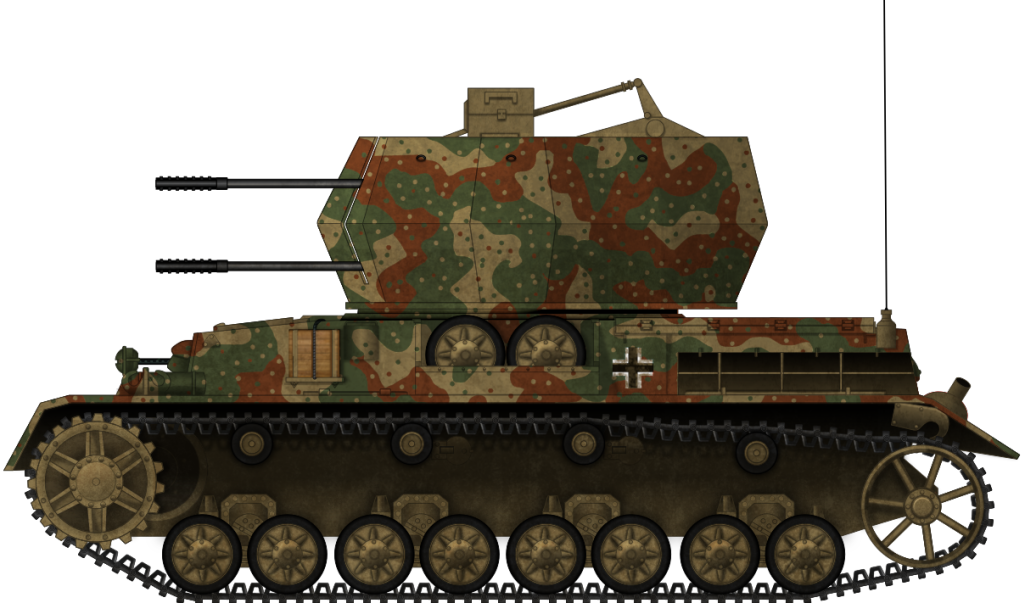
Turret
The Zerstörer 45 was more or less just an improved Wirbelwind, so it would have utilized many of the same components. The nine-sided open-topped turret’s overall design would likely have been the same, with some minor changes. It was open to the top in order to provide a better view of the surroundings and to reduce overall construction costs. This would have also helped remove the gun fumes properly, as the Germans never properly developed a full-enclosed anti-aircraft turret with an adequate ventilation unit. Each of these nine-sided plates was built by welding two angled armored plates. The lower plates were angled outwards and the upper ones were angled towards the inside. The angled armor provided some extra protection but, in general, it could only protect the crew from small-caliber weapons or splinters. The upper front armor plate, between the Flak barrels, had a small hatch that could be opened to allow the gunner to see and engage ground targets.

In order to make the construction of this vehicle easier, no extra traverse mechanism was provided. The turret was instead traversed by using the main gun traverse. The new turret was, in essence, just an extended gun shield. The ring-shaped turret base was welded to the hull top. To help with the rotation, ball bearings were added into this base, which made turret movement much easier.
Armor
Depending on the chassis used for the Zerstörer 45, there may have been slight differences in the armor thickness. In general, the later built Panzer IVs had a maximum frontal armor thickness of 80 mm. The sides were much thinner, at 30 mm, while the rear was 20 mm thick.
The turret armor protection would likely have been unchanged from the Wirbelwind, in the hope of saving development time and resources. If this is true, the armor thickness would have been 16 mm of all-around armor, with the top being completely opened. The side and front plates were placed at 21° to 27° angle. The rear plates were placed at a 14° to 20° angle
Armament
The most obvious change introduced on the Zerstörer 45 was the installation of the 3 cm Flakvierling anti-aircraft gun. This weapon was introduced to service (in single barrel version) as the 3 cm Flak 103/38 during 1944. It is also often named as the ‘Jaboschreck’,o which can be translated as terror or fright (Ger. Schreck) of the fast ground attack aircraft (Jagdbomber in German or just Jabo for short). In reality, if it would have lived up to its name is quite questionable. It was built as a combination of the aircraft-based 3 cm MK 103 cannon and the 2 cm Flak 38 mounting, mostly to get it in operational service as soon as possible and to be cheap to produce. In mid-1944, Rheinmetall-Borsig was tasked with the production of some 2,000 guns, in addition to 1,000 guns that were to be built by Gustloffwerke, but only small numbers were produced by the end of the war.
The 3 cm Flak 38 was a gas-operated and fully automatic gun capable of firing at 450 rpm, but the more practical rate of fire was 250 rpm. The 3 cm Flak 103/38 introduced a new belt-fed system which replaced the older 20 round magazine fed system. The maximum firing range at ground targets was around 5,700 m, while airborne targets could be hit at 4,700 m. It had a 360° traverse and -10° to +80° elevation.
Late into the war, a four-barreled version of the 3 cm MK 103, known as the 3 cm Flakvierling, was tested and possibly even built-in smaller numbers. Due to the late introduction, the overall characteristics of this four-barreled version are barely mentioned in the sources. Based on a few available photographs, it was provided with cylindrical-shaped magazines that were fixed to the gun but could be opened to place belt-fed ammunition inside of them. Another interesting feature was that these ammunition magazines were placed above (on the upper) and under (on the lower) guns, not on the side, like for the 2 cm four-barreled version.
Lastly, for self-defense, the crew could rely on the hull-mounted MG 34, retained from the Panzer IV design, and their personal weapons.


Crew
The crew of the Zerstörer 45 would likely consist of a commander/gunner, radio operator, driver, and one or two loaders. The driver and radio operator were placed in the vehicle’s hull. The positions of the remaining crewmembers are not listed in the sources. Given its gun’s main characteristics, their positions can be deduced. The 3 cm Flak38 commander/gunner position was to the rear of the gun. Given the use of a belt-fed system, it is possible that only a single loader would be placed in the turret. This seems plausible, given the general lack of manpower by 1945, but it would have greatly increased the reloading time of the main armament. On the other hand, the prolonged fire interval of the belt-fed system was probably sufficient to destroy or just drive off the attacking aircraft long enough for the crew to reload the main armament. In this case, the commander may have also helped to reload the armament faster. It is also possible that two loaders were placed in the turret too, each responsible for reloading two guns.

The Fate of the Project
According to author Walter J. Spielberger (Gepard: The History of German Anti-Aircraft Tanks), two such vehicles were built by the end of 1944. What happened after that is not clear. It appears that at least one of them was, alongside the Ostwind II, transported to the training center at Ohrdruf in Thuringia. If these vehicles were ever actually fully completed and if there were any defects with the overall design is unknown. Given their late introduction and unavailability of sources, this is unclear. Authors H. F. Duske, T. Greenland and F. Schulz (Flakpanzer IV Wirbelwind and Ostwind) mention that at least 6 ground mounts for the Zerstörer 45 were built. Author D. Nešić (Naoružanje Drugog Svetsko Rata-Nemačka), on the other hand, mentions that only one such vehicle was produced.
Conclusion
The Zerstörer 45 was another German World War Two design that is shrouded in mystery. While some sources claim that at least two were completed, it is not well known if the whole installation was viable. For example, the ground version of the 3 cm cannon, while effective when used against enemy aircraft, was noted to have a number of defects, such as strong vibrations during firing, which affected its precision, something the Germans tried to improve but never truly resolved. Given its late introduction, the chaotic state of Germany was in, with ammunition, manpower, and fuel in short supply. The Zerstörer 45 had great potential to be a good anti-aircraft weapon, at least in theory. In reality, the whole project was undertaken under harsh conditions of 1945 and was simply over-ambitious, without any real chance of getting into mass service.

Specifications |
|
| Dimensions (L-W-H) | 5.92 x 2.9 x 2.76 m |
| Total weight, battle-ready | 25 tonnes |
| Crew | 5 Commander/Gunner, Two Loaders, Radio Operator and Driver |
| Propulsion | Maybach HL 120 TR(M) 265 HP @ 2600 rpm |
| Range | 320 km on road; 210 km off-road |
| Primary Armament | Four 3 cm Flak 103/38 |
| Secondary Armament | MG34 machine gun |
| Armor | 10 to 80 mm |
Sources
- K. Hjermstad (2000), Panzer IV Squadron/Signal Publication.
- Engelmann-Scheibert, H. A. Koch, O. W. v. (1978) Renz Flak Auf Dem Gefechtsfeld Podzun-Palla-Verlag
- D. Nešić, (2008), Naoružanje Drugog Svetsko Rata-Nemačka, Beograd
- P. Chamberlain and H. Doyle (1978) Encyclopedia of German Tanks of World War Two – Revised Edition, Arms and Armor press.
- Walter J. Spielberger (1982). Gepard: The History of German Anti-Aircraft tanks, Bernard & Graefe
- Ian V.Hogg (1975). German Artillery of World War Two, Purnell Book Services Ltd.
- T. L.Jentz and H. L. Doyle (1998). Panzer Tracts No.12 Flak selbstfahrlafetten and Flakpanzer
- T. L.Jentz and H. L. Doyle (2010). Panzer Tracts No. 12-1 – Flakpanzerkampfwagen IV and other Flakpanzer projects development and production from 1942 to 1945.
- Walter J. Spielberger (1993). Panzer IV and its Variants, Schiffer Publishing Ltd.
- D. Doyle (2005) German military Vehicles, Krause Publications.
- H. F. Duske, T. Greenland and F. Schulz (2005) Flakpanzer IV Wirbelwind and Ostwind, Nuts and Bolts vol.13