 German Reich (1938-1942)
Heavy Tank – Paper Project
Getting a tank across obstacles is no small task, complicated by a series of factors of the physics of crossing a wall, a step, a river, or a trench. Those matters do not exist in isolation for a military vehicle and the obstacle crossing elements have to be weighed against the military needs, such as protection from enemy fire and being able to effectively deliver fire to the enemy. A long vehicle is better able to cross a wide gap, such as a trench or anti-tank ditch, but may then pay a price in being harder to turn and certainly a price in being a bigger vehicle with more machine to armor, meaning more weight. If, however, the vehicle could be made longer temporarily to cross an obstacle, it would result in having the obstacle-crossing abilities without the vehicle being permanently long. This might have a valuable military development. This is exactly the conclusion Johannes Eckard reached in September 1938, when he submitted his design for an extending track system for a tank to the German government.
The Man
The designer, Johannes Eckard, was from Freiburg im Briesgau in southwest Germany. In 1933, he filed a patent for an opening and locking device for double-glazed windows and, in 1936, another for a type of guide for using a saw. Neither had any obvious military utility, but were followed in September 1938 by an application titled Verlaengerbares Fahrzeug, insbesondere Kampfwagen mit Raupenantrieb (English: Extendable vehicle, especially a caterpillar-powered battle vehicle). The patent was granted for this vehicle over 3 years later, on 30th April 1942, and finally published a few weeks later, in June.
The Design
The vehicle shown in the design was surprisingly, not just a generic ‘tank outline’, and his track invention could not be retrofitted somehow to existing German tanks. In 1938, when he submitted that design, the Wehrmacht’s primary tanks were vehicles such as the Panzer I, Panzer II, and Panzer III, and none of those vehicles were able to be retrofitted with this type of track. The track units were supported from above rather than from the side and all of those existing designs had no substantial structure of the tank above their track units. With no ability to support the weight of a tank from a track guard, it can only be surmised that Eckard’s drawing was not only for his idea of a longer track system, but also of the outline of a tank which might make use of such a system.

Source: German Patent DE721474. Note that this image has been digitally cleaned by the author.
The basic shape of the hull seen from the side was somewhat rectangular, with a series of longitudinal steps in the side. Face-on, the vehicle body took the form of a ziggurat. The front of the hull was, unusually, raised higher than the rest of the hull, which sloped gently away towards the back end. From a short step on the side, it appears to have been drawn showing a weapon projecting from the side, which would be limited to firing forwards or to an arc across the front and side.
The turret was mounted on a raised section of superstructure that was curved at the front and angled at the rear, sloping very slightly as it rose away from the hull roof. On top of this was the turret, consisting of what appears to be a low and rounded shape, rather like that of Cold War era Soviet tanks. The main armament was mounted in the front of this turret.
In the ‘normal’ position, the tank’s profile was not particularly unusual and appears to have been running on eight road wheels, with an idler and sprocket at the ends of the track. Seen from the front, however, all sense of ‘normalness’ of the design disappears. The hull shape is that ziggurat shape on top and looks more like a space invader in profile, with two ‘arms’ projecting over the sides encompassing the running gear which is attached at the top under the arm. In the center of the hull, the outline provided by Eckard appears to show a completely flat bottom but is, in fact, bellied down between the two track units.

Source: German Patent DE721474. Note that this image has been digitally altered by the author.
Armor and Armament
Other than what can be assumed from the images, no information is suggested by Eckard about the armament for the tank. The hull seemingly has a machine gun on the left-hand side and, although the right side of the vehicle is not drawn, it can only surmised that the right side of the tank was likewise armed. No weapon is seen projecting from the front of the hull, so armament-wise, if the hull projection was meant to be a machine gun, then the design would be able to provide coverage fire at least forwards and maybe to the side.
It is unclear if these were meant to be fixed firing forwards or if some kind of mounting was considered, as nothing is mentioned in the patent. Given that a fixed machine gun has very little utility, a ball mount or even just a slot, as used on the Grosstraktor, would seem more sensible and likely allowing for an arc of machine gun fire perhaps as much as 45º to the side of each position.
No armament for the turret is mentioned either, but given the 1938 date, it somewhat limits the potential armament options. Logically, this vehicle would be fitted with some short gun and the drawing shows a barrel which has a pronounced wide and narrow part to it. Given the date and style of this gun, it may well be inspired by the Grosstraktor, which used a 75 mm. This would at least be commensurate with both the size of the vehicle and also the clear implication of a potential use for it as a heavier type used in assaults.

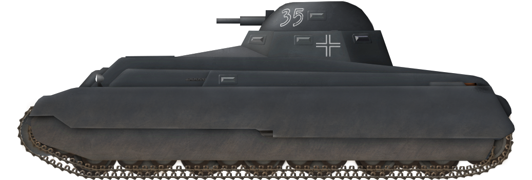
Source: Pinterest
Even if the Grosstraktor served as some kind of inspiration for Eckard, the armor likely could not be taken as being along the same lines. The Grosstraktor, for example, had surprisingly thin plating, 14 mm at its thickest, which was less than a WW1 British tank and barely bulletproof even when made out of good quality armor plate. In 1938, and certainly by 1942, for Eckard, such flimsy levels of protection were woefully inadequate even for small light tanks, such as the Panzer II with up to 15 mm, or the early Panzer III. The growth in protection on the Panzer III is perhaps the better example of what the armor should have been. By the early years of the war, this reached 30 mm and then 50 mm thick. This was enough to provide greater protection from enemy small arms and armor piercing bullets, but not anti-tank guns. Certainly, the side plates overhanging the tracks on Eckard’s design provide the appearance of a well protected vehicle.
Crew
As with the other features, no mention by Eckard was made of a crew for such a vehicle. Assuming the vehicle would eventually look roughly like what he drew if it had reached the stage of being built, then presumably it would need a driver and a commander, along with a crew member on each of the sides to operate the machine gun and at least one more to load and fire the gun. This would mean a crew of at least 5, and, if a loader was added, 6.
No indication occurred in the design for where the crew might even go but, logically, this would be the driver in the front, hull gunners on the sides, and the loader, gunner, and commander in the turret.
Engine
No suitable engine was discussed let alone suggested by Eckard for a vehicle of this type, as his primary focus was simply on the track system. There is no clear indication as to where the engine might be located. Nor is there an indication as to where the drive sprocket might be located on the design, although this would have to be at one end or another of the primary track.
Tracks and Suspension
The primary part of Eckard’s design was the track and suspension. This consisted of a top-supported track run of 8 road wheels as the ‘normal’ part of the track. Rigidly attached vertically to the overhang of the hull, the track unit itself had absolutely no sprung suspension drawn although, presumably, with rubber tyres on the wheels, there would be some cushioning effect. The speed of such a vehicle would therefore likely be fairly low, perhaps as little as 10 – 15 km/h. Beyond this, the vibrations and noise would make the vehicle hard to operate and create a lot of wear and tear on the automotive elements and crew.
On each side of this primary track run, there was an additional length of track formed around a hollow box work, with small road wheels fastened without suspension on the top and bottom. Thus, on each side of Eckard’s design, there were three full length track runs, with the center part with the large road wheels and with the small-wheel track units sandwiching it. Those side units were also suspended slightly above the level of the bottom of the center (primary) track unit, meaning that, on a hard surface, only those center tracks would be in contact with the ground. Traveling over soft ground, where the vehicle would sink a little, those side track units would come into contact with the ground and help to share the weight of the vehicle. It is unclear, however, if those supplementary tracks would be driveable in such circumstances or just act to spread the weight and rotate with the passage of the tank.
For all three sections of track on each side, the actual links appear to be very narrow, so that added together, the width of all three is more akin to a normal wider style of track. They had to be narrow to fit under each wing of the design.

Source: German Patent DE721474. Note that this image has been digitally cleaned by the author.
The clever part of Eckard’s design was not that these three units could work in this manner to spread the weight when on a soft surface, but that they could extend. These side units were attached to the center unit by means of a large pin, around which the boxwork part of the supplementary tracks sat. In the event of the tank having to cross a gap which it otherwise could not in its own length, then the exterior track would be thrust forwards whilst simultaneously the inner track was thrust to the rear. The amount of movement for the track was not fixed, but could be varied as required. Thus, over rough ground, it might be extended a little to cross the bumps, but when crossing wide gaps, the full length could be employed.

Source: German Patent DE721474. Note that this image has been digitally cleaned by the author.
This method allowed the vehicle to more than double its length in what would be three independent lengths of track. Here, it must be assumed that the supports for these track runs were both very substantial constructions and driven in some manner, as there is a conceivable risk that crossing a gap of roughly the original length of the vehicle could leave the tank itself completely suspended between both ends of the track and otherwise completely unable to free itself as the center (driven) track would be turning in thin air.

Source: German Patent DE721474. Note that this image has been digitally cleaned by the author.

Source: German Patent DE721474. Note that this image has been digitally altered by the author.

Source: German Patent DE721474. Note that this image has been digitally altered by the author.
Whether that possibility had occurred to Eckard is unknown or perhaps he was simply trying to think around the problem of making the tank long enough for just enough time to cross a gap. Either way, this was a substantial flaw or critique of his work and, other than the sheer complexity of making such a vehicle, if it were unable to perform the primary role for which it was intended, it would be useless.
Conclusion
As discussed, the track system offered a substantial potential advantage. In theory, a 6 m long tank would be able to cross just under half its length under normal circumstances, ~ 2.5 – 3 m. Faced with a gap 5 m wide, it would have to use bridging or a fascine of some sort. To cross such a gap, a tank would have to be over 11 m long and, other than crossing the gap, this length might be a hindrance for both shipping it and maneuverability on the battlefield. What Eckard offered was a potential way to make a tank which could be a ‘normal’ size for all other purposes and extra-long for those occasions when a wide gap needed to be crossed. What he designed, however, was a solution far too complex and unable to be retrofitted to existing vehicles, meaning a whole new tank would be needed right as Germany was reaching the peak of its power in WW2. There was simply no need for this vehicle, as there were no enormous obstacles for the Army to cross and anti-tank ditches or trenches they might need to cross were more easily handled with bridging equipment.
What became of Eckard is not known but, presumably, with this design not progressing or finding any interest from the authorities, he went back to his other engineering ideas. No examples of his tank or of a system like this are known to have been built or operated.
Specifications Eckard’s Extending Panzer |
|
|---|---|
| Crew | est. 5 – 6 (driver, hull gunner x 2 , loader, gunner, commander) |
| Dimensions | u/k |
| Engine | u/k |
| Speed | est. 10 – 15 km/h |
| Armor | est. 30 mm or more |
| Armament | 2 x machine guns in the hull, primary armament in turret |
Sources
German Patent DE628524, Kupplungs- und Feststellvorrichtung fuer Doppelfenster, filed 15th February 1933, granted 26th March 1936, published 6th April 1936.
Swiss Patent CH189205, Laubsägebogen, filed 1st May 1937, granted 28th January 1936, published 15th February 1937.
German Patent DE721474, Verlaengerbares Fahrzeug, insbesondere Kampfwagen mit Raupenantrieb, filed 24th September 1938, granted 30th April 1942, published 6th June 1942.
5 replies on “Eckard Extending Panzer”
what a beuty.
love this design
love the tank
When I think I have seen it all of the Reich’s tanks, Tank Encyclopedia drops another weird vehicle.
Wouldn’t this system break down all the time?
that is awsome