Categories
Cold War US Tech

Bar-Armor Experiments on M113 APCs in The Vietnam War

United States of America (1964-1965)
Add-on Armor – 8 Kits Made, 7 M113s and 1 M132 Converted

Vulnerability

The Armored Personel Carrier M113 was a simple vehicle. It was one of its strengths; simple, cheap, and adaptable. It found a wide variety of uses, but the lack of protection for the occupants was, for an Armored Personnel Carrier (APC), a very significant problem.
The aluminum armor on the box-shaped M113 was sufficient to protect from small arms fire, but was vulnerable to heavy machine-gun fire, and even more so to the High Explosive Anti-Tank (HEAT) rounds deployed by the Viet Cong (VC) and North Vietnamese Army’s (NVA) 57mm and 75mm recoilless weapons, as well as from Rocket Propelled Grenades. The VC had begun using the 57 mm HEAT round as early as summer 1963, with a dramatic rise in their use later that autumn. The rounds would easily penetrate the thin body of the M113, although, depending on where they hit, such as into the empty troop space, they sometimes did relatively little damage. By September 1963, the first 75mm HEAT rounds had been found by American forces in VC hands and in December that year, the first M113 was damaged by a hit from one. To make matters worse, mines were becoming increasingly popular by 1964. The recoilless rifles would, from 1965 onward, be replaced by rocket-propelled grenades, first the RPG-2, and eventually the RPG-7. Something needed to be done as the high level of vulnerability of the M113, the primary armored vehicle in service with US forces and of the Army of the Republic of Vietnam (ARVN) was a significant problem. Not only did the Americans and ARVN know this but so did the Viet Cong who had even published a document training guide in 1965, ‘Attack on M113APC’, detailing the best weapons and tactics to use.

M113 hit and penetrated by two shots from an NVA 57mm recoilless rifle firing HEAT rounds. Source: Starry

A Possible Solution

As early as July 1964, it was accepted that the vehicle was vulnerable to the recoilless weapon systems and the US Army Materiel Command (USAMC) began investigating additional armor which could be used to defeat these rounds. Their work was followed by the Ballistic Research Laboratory (BRL). In April 1965, BRL concluded, after exhaustive testing, that the solution lay in the use of bar armor panels attached around the vehicle. By July that year, the first prototype kit of this type of armor for the M113 had been manufactured, and by August 1965, eight further kits had been made and shipped to the Army Concept Team in Vietnam (ACTIV) for evaluation.
These 8 kits were then installed by the 80th Ordnance Rebuild Base Depot (80th ORBD) on M113 vehicles, with seven being used on standard M113 APC’s, and the eighth being fitted to the M113-based M132 Mechanized Flamethrower. Fitting these panels began on 8th October and was complete by 16th December 1965. Each kit required 105 man hours to fit to each vehicle.
The seven bar-armor equipped M113’s were issued to the 10th Armored Cavalry Squadron for the purposes of evaluation during their operations in the heavily jungled areas around Tay Ninh and Long An Provinces and the rice paddies of Hau Nghia Province. The single M132 fitted with the bar-armor kit remained with the 80th ORBD.
Each kit was made of several distinct parts. A large rectangular frame with one corner shaped to match the front profile of the vehicle was attached to each side by means of brackets sticking out of the side, which were fastened to the roof of the M113. Three such frames covered the front with one large, almost square frame covering the centre part of the hull and a tall-thinner frame on each side of the main one. Together, these frames covered the entirety of the sides and front of the vehicle.
As these armor kits increased the weight and thereby reduced the floatation of the vehicle, additional floatation was provided. This came in the form of a row of 5 large welded boxes attached to each side between the vehicle hull and the bar armor, and two large rectangular boxes welded along each front edge of the hull. As these boxes were hollow, they would provide the additional buoyancy required to counteract the weight of the armor kit. Tests later showed that, despite being slightly nose heavy, the kit did not hinder the M113 in the water.

Trials

The kits also had the undesired effect of increasing the bulk of the vehicle. The front frame projected 14 inches (356 mm) from the nose, requiring the driver to slow down prior to navigating a ditch. When he did not do so, the armor would strike the other side of the ditch and damage the bumper bar behind, which caused some of the grille bars to break and fall off. It was the same story for the width. Without the base armor kit, the base M113 was 105.75 inches (2.686 m) wide and could be reduced to just 100 inches (2.54 m) when the track guards were removed. When the bar armor kit was installed, even in the folded-in position, it was 112 inches (2.84 m) wide, which meant it proved to be too wide to cross standard Army bailey bridges in the Vietnam theatre. When the side frames were extended out to the desired position, 14 inches (356 mm) from the sides, the vehicle became 128 inches (3.25 m) wide which caused serious problems when traversing either the high grassy areas which could conceal obstacles or areas with trees.

The arrangement of the sections of bar-armor fitted. Source: ACTIV
Evaluation of the kits by the 10th Armoured Cavalry Squadron took place between 15th January 1966 and 15th April 1966, during which time, the unit undertook 36 combat operations in which they contacted enemy forces 10 times. M113 vehicles fitted were APC’s number ‘80945’, ‘81185’, ‘80952’, ‘81722’, ‘80951’, ‘81264’, and ‘80947’. All suffered damage from the terrain with only one suffering damage from enemy action.

Bar armor equipped M113 after striking anti-tank mine. Source: ACTIV


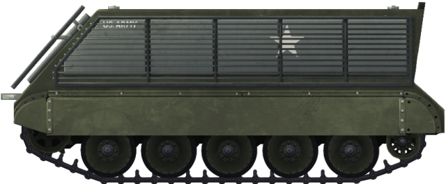
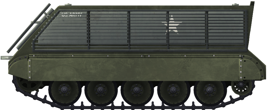
An M113 equipped with the Bar-Armor. Illustrated by Andrei ‘Octo10’ Kirushkin, funded by our Patreon Campaign.

Further Trials

The first trials of the 8 kits had been inconclusive, but two more kits were sent from the US to Vietnam, which, along with firing observation ports, were fitted to the vehicles assigned to the 2nd Armoured Cavalry Squadron in the Vietnam Delta. This unit was unable to use the bridges in their area with these kits, so instead, the vehicles were diverted to the 1st Cavalry Squadron (II Corps) north of Saigon.

Damage to the front of one M113 caused by striking terrain. Source: ACTIV

Damage to the top and bottom rotating arm mounts for the side frame caused when the frame struck terrain. Source: ACTIV

Damage to the side frames of the bar armor caused by striking terrain. Source: ACTIV

Conclusion

Although during the trial period the bar-armor was not fired upon by VC/NVA forces with recoilless weapons, the limited combat action which had been carried out had shown the vulnerability of the floatation boxes attached behind the bar armor. One vehicle using the kits was damaged by an anti-tank mine but was repaired fairly quickly. The damage from negotiating the terrain though was a problem and every one of the 7 vehicles initially tested suffered damage that way. It was the lack of enemy action against the armor and the excessive damage caused by negotiating the terrain which killed the project. Over the 3 month trial, no determination could be made by ACTIV as to the success or otherwise of the kits and the additional width and projection at the front of the vehicle limited the mobility of the vehicles. The bar armor was therefore abandoned in that form, it would have to be more durable to survive the Vietnamese terrain and no recommendation for this type of armor was issued for the US or ARVN forces.
It is hard to say how much the bar-armor could have reduced losses to the M113 in Vietnam had it been adopted or at least modified and adopted. Instead, the M113 received numerous minor modifications and the machine-gun cupola mount to improve its firepower instead. Whilst some crew did try using mesh netting as a field modification, no further official trials of these bar kits were undertaken. Between November 1967 and March 1970, the US and ARVN forces lost no less than 1,342 M113’s to enemy land-mines alone. Some 73% of vehicle losses in Vietnam were due not to recoilless rifles or RPG’s, but to landmines, and subsequent investigations into vehicle survival focussed on reducing the vulnerability of the M113 to mines, and its tendency to immolate the occupants when hit.

Sources

JRATA Project No.1B-172.0: Bar Armor Kit (M113)(U). (1966). Army Concept Team in Vietnam, US Army
Mounted Combat in Vietnam. (1989). General Donn Starry. US Government Printing Office
Don’t Harness an Ox to a Racehorse: Get the M113 out of the Armored Brigade Combat Team… Now, Please?. Col. William Nuckols and Dr. Robert Cameron

Categories
Cold War Austrian Tech Cold War French Tech Cold War Swedish Tech Cold War US Tech WW2 German Tech

Oscillating Turrets

Oscillating turrets were one of the latest trends in tank design in the early years of the Cold War, in the 1950s. The original intention of this type of turret was to make it easier to employ an automatic gun loader in the turret of a tank.
As well as the ability to fit an autoloader, there were other benefits. These included the ability to mount a big gun on a small chassis, have fewer crew members by the omission of the Loader crew member, and have a smaller turret. It also generally allows for a better front profile ballistically.

An AMX-13 90. The AMX-13s is perhaps the most famous and most successful tanks to use oscillating turrets. Photo: The Modeling News.

Design

Oscillating turrets consist of two parts that move on a separate axis. These are the top ‘roof’ section which holds the rigidly mounted main armament which moves up and down. In a conventional turret, the gun moves separately from the turret body, on its own trunnions.
The bottom ‘collar’ part is attached to the ‘roof’ via pivot joints and is fixed directly to the turret ring, allowing conventional 360-degree traverse.

History

Though it seems a relatively modern idea, the oscillating turret design actually goes back as far as the First World War, to a designer by the name of Arnold H. S. Landor. Landor, a British inventor living in Italy, who designed a new armored car in 1915. It featured possibly the first ever oscillating turret, which was armed with 65 or 75mm gun (specifics unknown) mounted on the vehicle’s roof. This was closely followed by an Armored car designed by Joseph Gonsior, Friedrich Opp, and William Frank. A joint project between the USA and Austro-Hungary from 1916, it had a machine gun in an oscillating turret. The elevation/depression was controlled via hand-cranks.
The next time such a component would appear would be in the early 1940s on the French armored car prototype, the Panhard 201. After the German invasion of France, the prototype was evacuated to northern Africa. This armored car was topped off with an oscillating turret that was manually operated and armed with an SA35 25mm gun.

The Panhard 201 with a simple oscillating turret. Photo: SOURCE
Late in the in the Second World War, the turret type was used again, this time as part of the German prototype Self-Propelled Anti-Aircraft Gun, the Flakpanzer IV Kugelblitz. This prototype was named after its turret; the name translates to “Lightning Ball”. It consisted of an armored ball mounted on an armored collar connected to the turret ring. The ball, mounting dual 30mm MK 103 cannons, moved independently in elevation, allowing it to target aircraft.
Post Second World War and during the early stages of the Cold War, the French began to lead the way in the development of this type of turret. They invested a great deal of time and money in designing such turrets for light tanks like the AMX-13 and armored cars such as the Panhard EBR (descendant of the 201). The French became the leaders in this technology and was the first (also one of the few) nation to employ this type of turret on a vehicle that saw active service.
Though they were never used on a serial production vehicle, the United States of America also began experimenting with oscillating turret designs in the late 1950s. Such turrets were developed for Light, Medium, and Heavy Tanks. Several prototypes were built to test these turrets, but they were never adopted. This was largely due to the fact that the Americans found no real advantage in using these turrets over the conventional format.

A scale model of the Kugelblitz produced by the designers. Photo: panzernet.net

Advantages

The major advantage of this type of turret was that it made the addition of an autoloader far easier becasue the loading system moves with the gun. In a conventional, rotating turret, an autoloader would have to follow the gun in elevation and depression to align the shell with the breech, and then ram it in. This method was used in the T37, an experimental American light tank. In other cases, such as with the Soviet IS-7 heavy tank, the gun had to be brought back to a neutral elevation after every shot, making engaging a target with multiple shots much slower. This is called the ‘index position’ and its an issue that remains to this day.
Oscillating turrets eliminated the hassle of both of these methods. As the gun was rigidly placed in the upper part of the turret, the autoloader, attached to the upper ‘roof’ section was free to ram shells in whatever the elevation angle the gun. Not only does this system speed up reloading but it allows the gun to stay on target during reloading which improves the speed of second and subsequent shots on target.
In a conventional turret, the breech of the gun sinks into the basket when elevated, meaning that the turret ring has to be of large enough diameter to accommodate this motion. With an oscillating design, the breach remains above the turret ring whatever the angle, meaning that the turret ring can be smaller, ergo, the hull can be smaller allowing for a bigger gun proportionally on a smaller vehicle. However, in this case, the maximum elevation angle is defined by the space between the rear of the turret and the deck of the hull, which may be less than the angles possible in a conventional design where the breach can fall into the hull.

Disadvantages

In this type of turret, the gun is often mounted high-up to grant as much room for elevation and depression as possible. Angles of fire though, were still rather limited when compared to traditional gun mounts. In elevation, the turret bustle would often be mere inches above the engine deck. Mounting the gun high in the turret gives a larger silhouette and easier to spot at distance than the lower-profile conventional turret. This is somewhat offset, however, due to the fact that in a hull-down position less of the turret would be exposed due the height of the gun mount and the improved ballistic shape of the turret
One of the biggest issues with oscillating turrets is that they could not be made safe against NBC (Nuclear, Biological, Chemical) attacks. Due to the to their design, there was a gap between the two moving sections of the turret. This was usually covered by waterproof canvas or rubber bellows that shrank and extended with the motion of the turret, but it was not an air-tight seal.

Outcome

The complexity of their design was the downfall of the oscillating turret, with most work on such designs coming to an end in the mid-1980s. To most military bodies, the opinion was shared that the turrets provided ‘no real advantage’ over the traditional format.
Autoloader technology had improved to the point of being compatible with a regular gun and turret layouts, removing the need for such turrets and the disadvantage of not being able to be sealed against NBC had remained a major and unresolved problem.
In 2013, however, a new vehicle with an oscillating turret entered service with the US Military. This is the M1128 Mobile Gun System (MGS). It consists of an unmanned, remote-controlled turret on the hull of the Stryker ICV (Infantry Combat Vehicle). The vehicle is armed with a 105mm M68A2 rifled gun, and is fed by an 8-round autoloader. It is currently one of the only vehicles with an Oscillating turret serving in an active Military.

The M1128 MGS with turret eleveated. Photo: WBS


French AMX-13 75.

Austrian SK-105 Kürassier

American 90mm Gun Tank T69

American Stryker based M1128 Mobile Gun System
Illustrations by Tank Encyclopedia’s own David Bocquelet

Tanks & AFVs with Oscillating Turrets

France

Panhard EBR: Armored car. In 1940, one of the pilot vehicles, the Panhard 201, was used in testing one of the earliest examples of an oscillating turret. Later models shared turret types and weaponry with the AMX-13. 1954, in service in France until 1981
AMX-13: A series of light tanks. Started out with a cylindrical oscillating turret with non-autoloading 75mm. This progressed to a longer, squarer turret with an autoloading system known as the FL-10. It is perhaps the most successful type of oscillating turret. Armaments progressed from a 75mm gun, to a 90mm and finally a 105mm gun. Entered service in 1952, in service with France until the 1970s, also in the arsenal of countries like Israel, Mexico and Singapore. Singapore only began to retire the tank in 2012.
Char Leger De 12 Tons: Competing design for a light tank, utilising a similar (if not the same) turret as the AMX-13. The major difference was with the running gear based on the classic German interleaved design. Early 1950s, no serial production.
AMX ELC EVEN series: A series of light tanks with various weapons including 30mm, 90mm and 120mm guns. The oscillating turret , consisted of a flat upper part on top of a ‘neck’ joint which was protected behind a truncated material cover. The weapons were often mounted off the center line at the extreme right or left of the turret. 1955, no serial production.
Batignolles-Châtillon Char 25t: Medium tank prototype designed along the same lines as the AMX-13s. It was armed with a 90mm gun and auto-loader. 1954, no serial production.
Lorraine 40t: Medium tank prototype with a unique suspension consisting of pneumatic road-wheels. It was armed with a powerful 100mm gun and autoloader. 1952, no serial production
AMX-50: A series of heavy tank prototypes. The earliest version borrowed much from the Lorraine 40t using a similar turret and the same 100mm gun and autoloading system. The later version incorporated a newer, larger turret design similar to that of the AMX-13’s known as the ‘Tourelle D’ and was armed with a 120mm gun. The AMX-50s borrowed the German style suspension with interleaved road-wheels. Early 1950s, no serial production.
Somua SM: A heavy tank design that competed with the AMX-50. It featured the same turret as the early AMX-50 prototype, armed with a 100mm gun fed by an autoloader. The hull design was heavily inspired by the Tiger II, but used a different individual wheel suspension instead of the famous interleaved type. Early 1950s, no serial production
Medium Tank M4 with FL-10: A number of surplus Sherman tanks were updated by adding the AMX-13’s 75mm armed FL-10 turret. Various models of Sherman were updated, including M4A1s and M4A2s. M4A2s with the turret were used by the Egyptian army in the Six-Day War. Mid-1950s, limited production.
Light Tank M24 with FL-10: A project to modernize M24s in France’s inventory by replacing the standard turret with the 75mm armed FL-10 of the AMX-13. 1956, no serial production

United States of America

Gonsior, Opp, and Frank War Automobile: A joint armored car project designed by Joseph Gonsior, Friedrich Opp, and William Frank. A joint project between the USA and Austro-Hungary from 1916, it had a machine gun in an oscillating turret. The elevation/depression was controlled via hand-cranks. Never left blueprint stages. 1916, no serial production.
76mm Gun Tank T71: A light tank design by two competitors. These were Detroit Arsenal (DA) and Cadillac Motor Car Division (CMCD). DA’s design utilised an oscillating turret and autoloader feeding a 76mm gun. The vehicle was never built and never left blueprint stages. Early-1950s, no serial production
90mm Gun Tank T69: Medium Tank prototype with an oscillating turret mounted on the hull of the failed T42 medium tank project. The turret contained an 8-shot cylinder, not unlike a giant version of one you would find on a handgun. Only one was ever built as the turret was not thought to provide “any real advantage” over the traditional type. Mid-1950s, no serial production.
105mm Gun Tank T54E1: Medium tank prototype produced for series of trials to find the best way to mount a 105mm gun on the hull of the M48 Patton III. An autoloader system was also utilised inside the turret. Mid-1950s, no serial production.
155mm Gun Tank T58: A heavy tank design utilising an oscillating turret with autoloader, mounted on the hull of the T43/M103 hull. Had the tank left the drawing board, it would’ve been armed with a 155mm gun, the largest gun to be mounted in an oscillating turret. Mid-1950s, no serial production.
120mm Gun Tank T57: A heavy tank design similar to the T58 but armed instead with a 120mm gun. Mid-1950s, no serial production.
120mm Gun Tank T77: A heavy tank project to mounting the T57’s turret on the hull of the M48 Patton III. Mid-1950s, no serial production.
M1128 Mobile Gun System: The latest American vehicle to use this turret type. It consists of an unmanned, remote turret on the hull of the Stryker ICV (Infantry Combat Vehicle). The vehicle is armed with a 105mm M68A2 rifled gun, and is fed by an 8-round autoloader. 2013, currently serving.

Austria

SK-105 Kürassier: Austrian light tank. The hull was an indigenous design, but it utilized the turret of the AMX-13 bought from France. They were armed with 105mm guns. Early 1970s, in service with Austria until the 1990s, remains in service countries such as Argentina and Botswana.

Sweden

EMIL Project: A series of heavy tank designs with heavily armored oscillating turrets. They were designed with autoloaders and guns from 105mm to 150mm. Two chassis, codenamed “Kranvagn” (English: Crane vehicle) were constructed before the project’s cancellation. Early 1950s, no serial production.
Strv m/42-57 Alt. A.2.
In an effort to up-gun their already vastly outdated Stridsvagn m/42. A meeting was held on February 15th, 1952 on possible improvements. One solution was to mount a new oscillating turret design on to the m/42’s hull. This idea never came to fruition, however.

Germany

Flakpanzer IV Kugelblitz: Anti-aircraft tank built on the chassis of the Panzer IV. The tank was named after its turret, the name meaning “Ball Lightning”. It was armed with two 30mm MK 103 auto-cannons. 1943, no serial production.
DF 105 Combat Tank: A cooperative project between France and Germany combining the Marder I chassis with an updated AMX-13 turret with a 105 mm main gun. It was called the DF 105 Combat Tank. Early-mid 1980s, not serialized. Mid-1980s, no serial production.
CLOVIS, FL-20, 105mm: A follow up project of the DF 105. The Marder chassis remained the basis, but a completely new oscillating turret was added. It was possibly one of the last turrets of the type to be developed. 1985, no serial production.

Great Britain

COBRA: A design for a 30-ton tank to carrying a 120mm gun. It was extremely lightweight for a tank with such a gun, but retained excellent armor protection over the entire frontal arc. Side and rear armor were sacrificed, however. 1954, no serial production.

Italy

AMX-13/60: An update program that replaced the existing gun of the French Light Tanks with a high-velocity 60mm gun.

Links, Resources & Further Reading

www.chars-francais.net
www.armchairgeneral.com
Panzer Tracts issue 12–1: Flakpanzerkampfwagen IV and other Flakpanzer projects development and production from 1942 to 1945, Thomas Jentz & Hilary L. Doyle.
Presidio Press, Patton: A History of the American Main Battle Tank, Volume 1, R. P. Hunnicutt
Presidio Press, Firepower: A History of the American Heavy Tank, R. P. Hunnicutt
Rock Publications, the AMX-13 Light Tank. Volume 2: Turret, Peter Lau
The Tank Museum, Bovington, UK
The National Armor and Cavalry Museum (NACM), USA
Musée des Blindés, Saumur, France