Categories
Cold War US Other Vehicles

Self-Propelled Flame Thrower M132 ‘Zippo’

United States of America (1959)
Armored Flamethrower – 351 Built

Since its appearance in the late 1950s, the Armored Personnel Carrier (APC) M113 has continued to be one of the most versatile and universal armored vehicles to have ever existed. It has spawned numerous variants in its long service life, from mobile command posts and Self-Propelled Anti-Air Guns (SPAAGs) to firefighting vehicles.

One of the less well-known variants was the Self Propelled Flame Thrower M132. Entering service in 1963, the M132 – along with the Flame Thrower Tank M67 ‘Zippo’ – would be one of the last armored or ‘mechanized’ flamethrowers to see service in the United States Military. Whereas the M67 would serve in the US Marine Corps (USMC), the M132 would serve with the US Army. The vehicle saw action during the long years of the Vietnam War (1955-75), but its time in service was, however, short-lived. This is mostly due to the fact that, after Vietnam, flame throwing vehicles began to fall out of favor.

One of the first things the article will address is its unofficial ‘Zippo’ nickname – named after the lighter brand – which it shares with the M67. Its origin is somewhat mysterious. Just like the M60A2 tank and its ‘Starship’ name, a concrete source cannot be stated as to when this name came into use. It was likely given by the crews or infantry that operated with the vehicle. There is a suggestion, however, that the name originated from this particular lighter being used to ignite the napalm fuel when the electrical igniters failed.

The M113-based Self-Propelled Flame Thrower M132 ‘Zippo’. Photo: Hunnicutt Bradley

The M113

The M113 is one of the most famous Armored Personnel Carriers ever built and continues to serve in not only the US Military but also in the inventory of many of the world’s militaries. The vehicle has been in service for 60 years, making it one of the longest-serving armored vehicles in history.

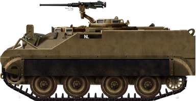
Developed and built by the Food Machinery Corporation (FMC), the M113 is a basic vehicle, little more than an armored box on tracks. It is 15 ft 11.5 in (4.8 m) long, 8 ft 9.7 in (2.6 m) wide, and 8 ft 2 in (2.5 m) tall. The vehicle’s structure is almost completely fabricated from aluminum, including the armor which is between 0.4 and 1.4 inches (12 – 38 mm) thick. The vehicle started out with a Chrysler 75M petrol engine, although this would later be changed to a General Motors 6V53 diesel type. The power plant is located at the front of the vehicle with the transmission. The vehicle is supported by a torsion bar suspension connected to five road-wheels. The idler wheel is at the rear with the drive sprocket at the front.

The APC has a crew of two, a Driver and a Commander, who are located at the front of the vehicle, with a passenger compartment taking up the rear of the vehicle. Eleven passengers can be carried by the vehicle. The APC’s usual armament would be a single Browning M2 .50 Cal (12.7mm) heavy machine gun, located at the commander’s position.

Development & Background, the CRDL

In June 1954, the Chemical Research and Development Laboratories (CRDL) began a study, conceptualized by the US Army Chemical Corps, looking into the conversion of serving tanks and armored vehicles into armored/mechanized flame throwers. As a result of this study, the E31-E36 flame thrower kit was developed. The nomenclature, which was unchanged from its debut in the Second World War, denotes that this is the combination of the E31 fuel and pressure unit and the E36 flame gun. The idea behind this kit was that it could be installed on serving vehicles with minimal effort.

One of the M59 prototypes during a demonstration for President Kennedy in 1961 at Fort Bragg. Photo: LIFE Magazine

Three E31-E36 kits were produced and tested on the M59 APC, the predecessor of the M113. In the M59, flame-fuel capacity was 400 gallons (1,818 liters) providing a total firing time of 70 seconds. Following the tests, improvements were made to the weapon and it received the new designation E31R1-E36R1. The modifications to this version of the weapon were intended to allow its installation not only on the M59, but also the brand new M113 APC.

Diagram showing the internal arrangement of the flame thrower system inside the M113. Photo: Hunnicut Bradley

Prototypes

In the summer of 1959, a contract was signed for the construction of three E31R1-E36R1 units and their installation aboard three M113s. The newer, and larger, M113 was found to be a far more suitable vehicle than the M59 and, as such, all work on an M59 based flame thrower ceased. This is despite the M59 having better flame fuel capacity, and as such, a longer firing time*. Logistically, however, it was only prudent to develop the vehicle on a new type which was then entering service. This would allow a degree of commonality, making it easier to manufacture and allowing spare parts to be shared between vehicles.

The three prototypes had the E36R1 installed inside an M1 Cupola – the machine gun armed cupolas found on the M48 and M60 tanks – with a coaxial machine gun. This cupola was then mounted over the commander’s position, with the fuel and pressure systems installed in the personnel compartment. Initially, the coaxial machine gun consisted of the .50 Cal (12.7mm) M85, this was later changed to the .30 Cal (7.62mm) M73.

Production artwork of the M132. The configuration of the flame projector in the cupola with the coaxial machine gun is clearly visible. Photo: Hunnicutt Bradley

Testing of the prototypes took place in 1961 at Fort Benning, Georgia, and Fort Greely, Alaska. In March 1962, the E31R1-E36R1 was standardized by the Chemical Corps Technical Committee (CCTC) as the M10-8. This nomenclature denoted the M10 fuel and pressure unit, and the M8 flame gun or ‘Cupola Group’. A year later, in 1963, the United States Army Materiel Command (AMC) officially type-classified the vehicle as the Self-Propelled Flame Thrower M132. In December of 1963, a new Diesel powered version of the M113 was nearing the end of its development, this would become the M113A1. The natural progression for the M132 was for it to be built on the hull of the new M113A1. The new version was classified by the AMC as the M132A1. The M132A1 was also known as the ‘Standard A’ with the earlier M132 version known as the ‘Standard B’.

Overview of The M132

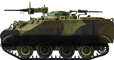
In total, the Food Machinery Corporation (FMC) would produce 351 vehicles, consisting of 201 M132s, and 150 M132A1s. The M132 was operated by a two-man crew consisting of the driver, front and left, and the flame gunner/commander, located behind the driver in the center with the flame gun. Overall, the dimensions of the M113 chassis were unchanged. It remained 15 feet 11 ½ inches (4.8 meters) long and 8 feet 9 ¾ inches (2.6 meters) wide. Due to the flame cupola, it is 2 ¼ inches shorter than the standard M113 at 7 feet 11 ¾ inches (2.4 meters) in height. This is due to the lack of a mount for a machine gun. The M132 retained the M113’s top speed of 42 mph (68 km/h).

Flame Equipment

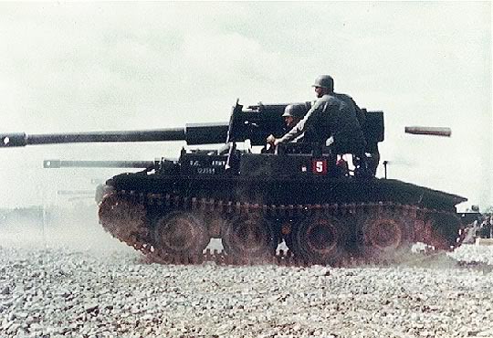
In the cupola, the M8 flame projector is mounted on the left with the coaxial M73 .30 Cal (7.62 mm) machine gun on the right. The barrel of the projector is flat with a sausage-like aperture. The cupola is traversed by hand and has a 360-degree arc of rotation. Both the machine gun and flame gun share a vertical traverse of +55 to -15 degrees. The cupola was equipped with 4 vision blocks and an M28D sight for the flame gunner/commander.

Front view of the M8 cupola group atop the M132. Note the M73 7.92mm machine gun on the left, and the flame gun on the right. The flame gun has a flat barrel, with a sausage-like muzzle. Photo: Public Domain

The flame gun is fed by the M10 fuel and pressure unit, located in the rear of the vehicle in what would be the personnel bay of the standard M113. The drop ramp was retained on the M132 to allow easy access and refueling to the weapon systems. The M10 unit took the form of four snowman-like structures, consisting of a large, spherical 50 gallon (227 liters) pressurized fuel tank with a smaller, spherical compressed air tank on top. The fuel tanks were pressurized to 325 pounds per square inch (23 kg/cm²), with the air tanks pressurized to 3,000 pounds per square inch (210 kg/cm²). The fuel tanks are connected in series, with the last one connected to the rotating joint of the cupola group. The air tanks are also connected together and provide pressure for the flame gun and fuel tanks. The tanks were placed in a removal rack system to allow easy maintenance for both the tank system and the internal components of the vehicle.

Diagram of the snowman-shaped fuel and air units located in the rear of the M132. The large balls on the bottom contain the flame fuel, the smaller balls on top contain pressurized air. These components were all mounted to a single rack system to allow easy removal. Photo: Hunnicutt’s Bradley

In total, the M132 could carry 200 gallons (909 liters, *the dropped M59 version could hold 400 gallons/1818 liters) of thickened, gasoline-based flame fuel. This fuel could be propelled to ranges of 12 to 218 yards (11 to 200 meters).

Service

Where its bigger brother, the M67, found service almost exclusively with the United States Marine Corps (USMC), the M132 would enter service with the US Army, specifically in Armored Cavalry units. Based on ensuing combat experiences, the Army Concept Team in Vietnam (ACTIV) advised that four M132s and two regular M113s be attached to each regiment. Headquarter companies of U.S. Armor and Cavalry units were all assigned at least one M132. Also, armored regiments of the Army of the Republic of Vietnam (ARVN, Viet: Lục quân Việt Nam Cộng hòa) were all assigned four M132s. The M132s were not limited to the US Army, however. Specific tactics were drawn up for operations with both the Army and Marine Corps, but also for the Navy.

Close up of the flame gun in action. This photo was taken with the Vietnam version of a ‘selfie-stick’. This being a camera attached to a metal pipe slotted over the coaxial M73 machine gun. Photo. LIFE magazine

Standard combat procedure for the M132 was thus: 1) the M132 would advance on a target, using the coaxial M73 machine gun to suppress the target. 2) continuing to fire, the vehicle will move into flamethrower range of the target. 3) the flame gun is fired. In some instances, this may first consist of a “wet burst” of unlit fuel, which would then be ignited by a second ignited burst. The “wet burst” method had been in use since the Second World War. Flame tanks, whether it be the Churchill Crocodile or POA-CWS H1 Sherman, would fire unlit fuel at defensive positions, allowing it to ‘soak’ into the structure. The second lit burst would then ignite the first burst, burning out the defenders. Due to the location of the flame gun behind the driver’s position, it was recommended that the driver keep his hatch closed in combat, for obvious reasons.

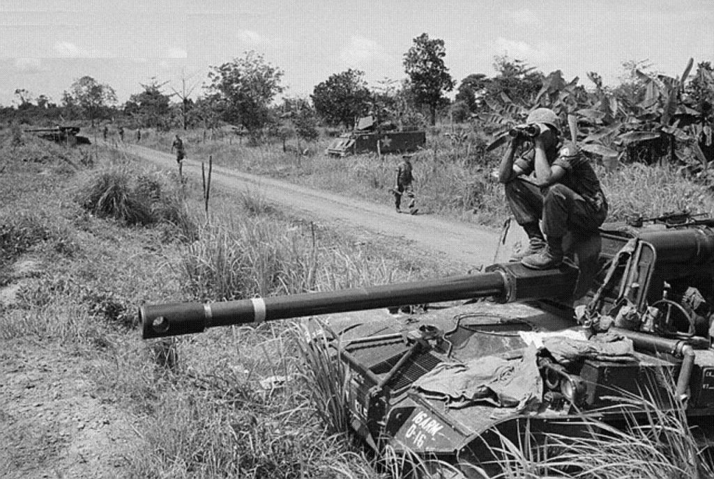
Due to the vehicle’s thin, aluminum armor, it was relegated to a strictly support role, operating only with the protection of infantry or armored support. Even so, the vehicle was a valuable asset to convoys. It served as protection against hidden attackers in the heavily vegetated roadsides of the Vietnamese jungle. There is also a recorded example of an M132 knocking out a Vietcong 57mm recoilless rifle team with a 3-second flame burst during the Battle of Ap Tau O in 1966.

M132 of 1/4th Cavalry “The Quarterhorse”, 1st Infantry Division “Big Red One” during Operation Cedar Falls. This M132 is burning a field in the “Iron Triangle” region of Ben Suc, January 1967. Photo: Jerzy Krzemiński

Unfortunately, not too much more is known about individual battles or skirmishes the M132 may have taken part in. The Vietnam War would be the only conflict that the M132 saw service in. The small paragraph below from the US Army report ‘Mechanized and Combat Operations in Vietnam’ published in March 1967, gives a little detail on the vehicle’s use in the conflict:

The M132 mechanized flame thrower has been successfully employed in offensive and defensive operations in Vietnam. In search and destroy operations, they are normally employed in pairs against bunkers and densely foliaged enemy-defended areas containing antipersonnel mines and booby traps. Flame directed at such areas may not destroy a protected enemy, but heat detonates mines and defoliates the area. In defensive positions, the flamethrower is employed to fill gaps not covered by direct fire weapons and to illuminate the area. During movements, the M132s can provide close-in flank protection to the column…

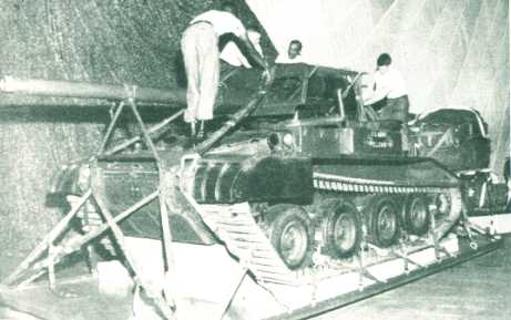
When being used in Naval operations, M132s would be backed onto Armored Troop Carriers (ATC, converted LCM-6 vehicle carriers) accompanied by a 2 ½ ton refueling truck. The M132s would fire over the sides of the vessel at targets on the river bank. There is at least one recorded example of this taking place on the Mekong River.

An Armored Troop Carrier (ATC) on a Vietnamese River, note the M132 in the cargo area at the front of the vessel. Photo: Photo: NHHC Photograph Collection, L-File, Vietnam
An M132 unleashes its firey breath at a river bank from the deck of an ATC. Photo: Quora.com

An Unquenchable Thirst

In operations, the M132 was accompanied by a specially adapted variant of the M548 Cargo Carrier. This was the Flame Thrower Service Vehicle XM45E1. As the M132 had such a small flame fuel capacity, it had a short burn time of just 32 seconds (*the dropped M59 version had a 70 second firing time). The XM45E1 was designed as a refueler for mechanized flamethrowers. The vehicle could mix and transfer thickened flame fuel. It also had an air-compressor to replenish air tanks and carried spare flame system parts. As well as the M132, the XM45E1 also supported the M67, but to a lesser extent.

The Flame Thrower Service Vehicle XM45E1. Photo: Hunnicutt’s Bradley

Fate

The M132 was a successful vehicle. Modified versions of its M10 flame turret even went on to be used on some smaller naval vessels. Despite its success, the M132 would share the same fate as the M67 Flame Tank, being one of the last mechanized flamethrowers to serve with the US Military. The M132 and M67 would be completely phased out by the early 1980s, by which point the controversial weapons had largely fallen out of favor in many of the world’s militaries due to humanitarian reasons. Flamethrowers were controversial with the operators as well as those on the receiving end. They were dangerous to use and the injuries caused by them were horrific. The United States officially stopped using all flamethrower types in 1978 and continued to phase them out after that date. The reason stated at the time was: “flamethrowers were not effective in modern combat scenarios”.

One of the later ATC that had turrets from the M132 installed. Photo: Michael Moore

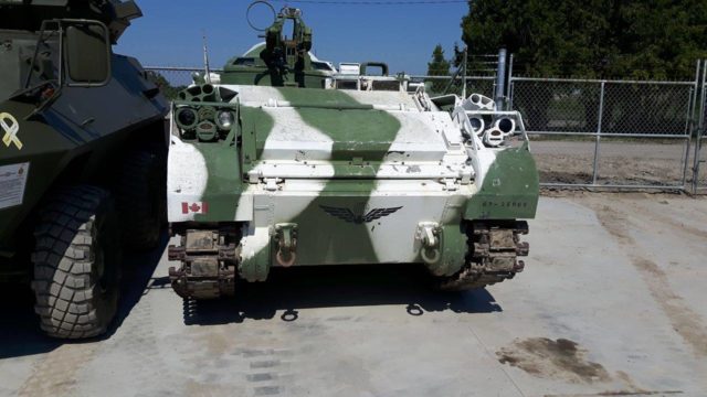
A few M132s survive to this day. One can be found in Vietnam at the War Remnants Museum in Ho Chi Minh City (formerly Saigon). One of the only surviving examples in the US can be found at the United States Army Chemical Corps Museum at Fort Leonard Wood, Missouri.

Surviving M132 at the War Remnants Museum in Ho Chi Minh City, Vietnam. Photo: Wikimedia Commons


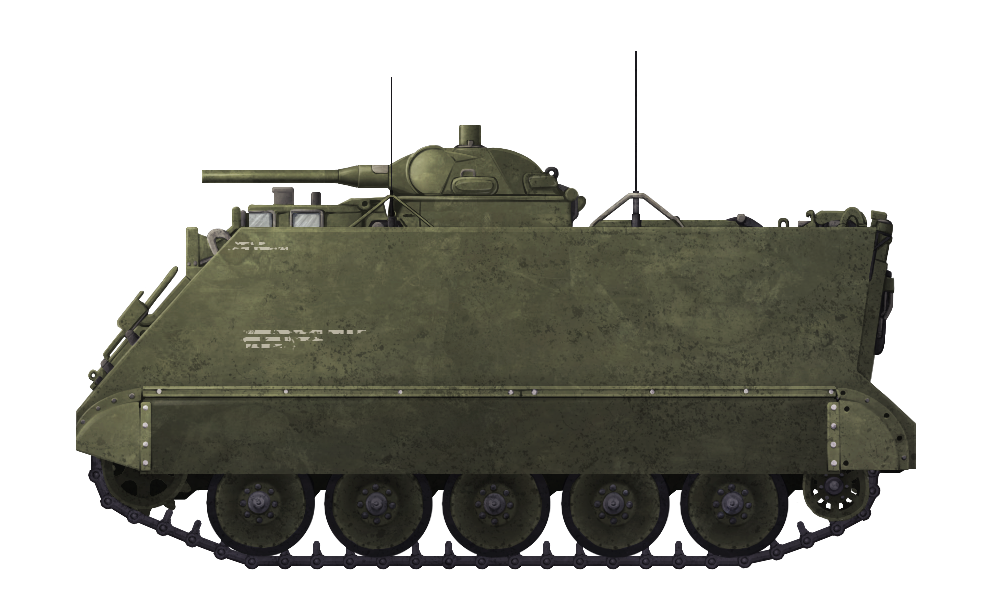
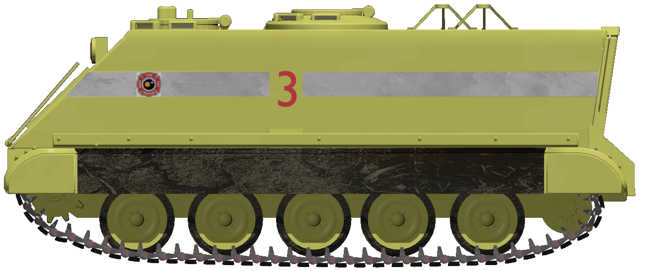
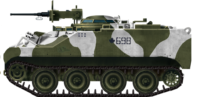
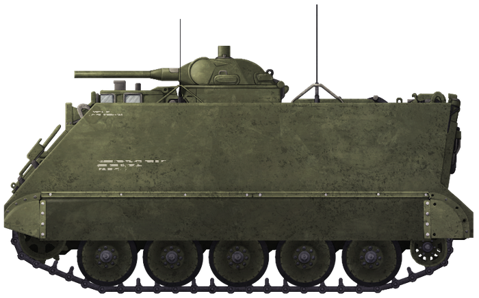
Illustration of the Self-Propelled Flame Thrower M132 ‘Zippo’, produced by Andrei ‘Octo10’ Kirushkin, funded by our Patreon campaign

M113 APC specifications

Dimensions (L-w-H) 4.86 x 2.68 x 2.50 m (15.11 x 8.97 x 8.2 ft)
Total weight, battle ready 12.3 tonnes (24,600 lbs)
Crew 2 (Commander/Gunner, Driver)
Propulsion Detroit 6V53T, 6-cyl. diesel 275 hp (205 kW) P/w 22.36 hp/tonne
Transmission Allison TX-100-1 3-speed automatic
Maximum speed 42 mph (68 km/h) road/3.6 mph (5.8 kph) swimming
Suspensions Torsion bars
Range 300 miles/480 km
Armament Main: M10-8 Flame thrower system.
Sec: Coaxial M73 .30 Cal (7.62mm) Machine Gun
Armor Aluminum alloy 12–38 mm (0.47–1.50 in)
Production 351

Sources

R. P. Hunnicutt, Bradley: A History of American Fighting and Support Vehicles, Presidio Press
Michael Green, Images of War: Armoured Warfare in the Vietnam War, Pen & Sword Publishing
Captain John Ringquist, U.S. Army Flamethrower Vehicles Part 3, Army Chemical Review
Fred W. Crimson, U.S. Military Tracked Vehicles, Motorbooks International
Armored Fighting Vehicle Data Base
www.globalsecurity.org
www.revolvy.com


Categories
Cold War US Other Vehicles Has Own Video Modern US Other Vehicles

NASA M113 Armored Rescuer

United States of America/NASA (1960s-2015)
Rescue Vehicle – 4 Operated

From the days of the Mercury space program, the means of evacuating astronauts from a burning or otherwise compromised rocket vexed the National Aeronautics and Space Administration, better known just as ‘NASA’. The problem was to get the astronauts from the rocket and to safety as fast as possible. The standard means chosen was to use a zip-line to get the astronauts from the rocket (or later from the shuttle) to a concrete bunker from where they would be driven to a safe distance.
The nature of the contingency being unique meant a unique solution was required which came in the form of the M113 Armored Personnel Carrier (APC). An armored vehicle would allow rescue crews to get to and from the scene and evacuate astronauts safety regardless of falling debris. At least 4 M113 vehicles were obtained. In 2013, upon the announcement of their retirement, it was confirmed that the 4 new vehicles had been obtained to replace the M113’s. This suggests that just the 4 M113’s had been used by NASA at the Kennedy Space Center, Cape Canaveral, Florida.

Two early M113 NASA Armored Rescue vehicles. The one nearest the camera has a rectangular shield at the front and is coated with what is believed to be heat resistant asbestos based paste.
Photo: ‘Alacrity’ at AR15.com
 
 
Mercury-era NASA M113 with Cape Canaveral Fire Department.
Photo: Bisney and Pickering

Modifications and Colour

There is some information suggesting that early work with the M113’s involved the use of asbestos added to the exterior either as a paste or as panels bolted on with the intention of protection from the potentially intense heat and flames which might be faced by such as a rescue operation. Photographic evidence of these early vehicles merely shows initially no numbers and at least one vehicle with some kind of coating (see above) and a large rectangular shield at the front. The color of the vehicle is not known and later they can be seen in a dark color but with large numbers painted on the front and sides (and presumably the rear).

NASA M113 Vehicle No.1 during shuttle launch showing the all-white colour but with the ramp open.
Photo: NASA

Vehicles 1 and 3 noticeably had a large cab type structure added to the roof over the commander’s hatch at the time. Later photos from the 1970’s show the vehicles painted in a white color with large red numbers. Photos taken in 2014/2015 when the vehicles were being retired showed a more common firefighting luminous-green color with a horizontal reflective stripe and red numbers.

Vehicles No 1 and 2.
Photo: NASA
 
 
NASA’s M113 based armored rescuer. Illustrated by William ‘Richtor’ Byrd, funded by our Patreon Campaign.

Use

The procedure for using these vehicles at the time of their retirement was that Vehicles 1 and 2 remained on standby at a secure location less than one mile (9/10th of a mile) from the launch site. A third vehicle was kept available, open and uncrewed next to the astronaut’s evacuation bunker. Vehicles 1 and 2 were crewed during launch time with a crew of fully equipped firefighters in silver firefighting suits with self-contained breathing apparatus on.

NASA M113’s Vehicles No.1 and No.3 by the evacuation bunker during launch.
Photo: capcomespace.com

Immediately prior to launch, the fully equipped firefighting crew cram into the vehicle while the driver remained outside. He would enter the vehicle at the time of the emergency call. The rear ramp on the M113 would be raised and it would set off on its rescue mission. The reason for this is to do with air supply. Once sealed, the crew of Vehicles 1 and 2 have just 10 minutes to get from their starting point to the launch site, effect a rescue, reenter the vehicle and then get away. 10 minutes is not long at all especially considering the inferno which probably awaits them and the crews train tirelessly to hone their response times because seconds matter. Vehicle 3 sat at the reception point for astronauts by their bunker with the rear ramp open to expedite the astronauts’ evacuation via the slide wire baskets into the bunker. Because Vehicle 3 was a self-evacuation vehicle, all astronauts were trained to operate it.

NASA M113 Vehicle No.2 seen during training as firefighters enter, and a view of the interior of one of the vehicles showing the cramped interior when closed up. Photos: NASA

Photographic evidence shows that over the decades the exact positioning and response for the vehicles had evolved but the essential requirement was the same, evacuating the astronauts in the event of a launch disaster.

Current Status

As of December 2013, the old M113’s were replaced by a more modern alternative, surplus Caiman Mine Resistant Ambush Protected (MRAP) trucks. The M113’s were never used in a real-life rescue. The MRAPs are faster and more spacious than the M113 and just as well protected. The only modification to the Caiman, other than being painted white, is the planned addition of a rear ramp replacing the original steps. However, as of 2015, the Caiman vehicles seen at NASA retained the rear steps and doors. Just like the M113’s, 4 Caimans now fulfill the rescue role for NASA. The status of the M113’s is unknown although Vehicle No.1 can now be seen on a concrete platform outside Kennedy Space Center as a display.

NASA Caiman MRAP (without ramp modification fitted) next to NASA M113s #1 and #2.
Photo: NASA

Specifications

Dimensions (L-w-H) 4.86 x 2.68 x 2.50 m (15.11 x 8.97 x 8.2 ft)
Total weight, battle ready 12.3 tonnes (24,600 lbs)
Crew 5 (Commander, Driver, 3 Firefighters/EMT’s)
Propulsion Detroit 6V53T, 6-cyl. diesel 275 hp (205 kW) P/w 22.36 hp/tonne
Transmission Allison TX-100-1 3-speed automatic
Maximum speed 42 mph (68 km/h) road/3.6 mph (5.8 kph) swimming
Suspensions Torsion bars
Range 300 miles/480 km
Armor Aluminum alloy 12–38 mm (0.47–1.50 in)

Links, Resources & Further Reading

www.nasa.gov
M113s Give Armored Ride to Firefighters, Steven Siceloff
Spaceport News, Vol.51. No.6 April 1st 2011
Spaceshots and Snapshots of Projects Mercury and Gemini: A Rare Photographic History, Bisney and Pickering

Categories
Cold War US Other Vehicles

Medium Tank M4A3 (105) HVSS ‘Porcupine’

United States of America (1950-1953)
Communications Tank – 2-5 Converted

Ever since the earliest days of tanks and armored vehicles, special radio communications variants have been produced. After all, communication is, perhaps, the most important aspect of any military operation. Whether between infantry, airforce or armor, communications are key to a successful operation and maximizes coherence between various units. The earliest of these vehicles was the ‘Wireless Communications Tank’ based on the British Mk. I tank used in the First World War. In the Second World War, more appeared such as the German Kleiner Panzerbefehlswagen based on the Panzer I, and the Japanese Shi-Ki based on the Type 97 Chi-Ha.
In the Korean War (1950-1953), communication was key with Allied forces spread all over the ‘Land of the Morning Calm’, as it was called by the Korean people. With friendly forces always on the move, units realized there was a need for compact and mobile radio communication stations.
By the time of this War, the Medium Tank M4 was a largely outdated and plentiful vehicle to base such a vehicle on. This conversion became known as the ‘Porcupine’ after the multiple antennae that protruded from the tank. It was an extremely rare vehicle, and it is believed that only two to five of these field-conversions were produced.

Porcupine ‘Y53’, south of Panmunjom on 27th June 1952. Photo: Presidio Press

Medium Tank M4A3 (HVSS)

By the time of the Korean War, the M4 series had evolved into its final form, often referred to as the M4A3E8. To the Marines in Korea, they were known as the “Old Reliables”. Entering service late in the Second World War, this model featured an improved Horizontal Volute Spring Suspension (HVSS) that replaced the iconic Vertical Volute Spring Suspension (VVSS) of earlier models. This suspension allowed for a wider track, improving grip and lower ground pressure on softer ground.
Propulsion was provided by the Ford GAA all-aluminum 32-valve DOHC 60-degree, 525 HP, V8 gasoline/petrol engine. This could propel the tank to a top speed of 40 – 48 km/h (25 – 30 mph). Armor on the vehicle was up to 76 mm (3 in) thick. The tank had a crew of five, consisting of a commander, driver, co-driver/bow machine gunner, gunner, and loader.
Although a large number of the newer, 90mm gun armed M26 Pershings and M46 Pattons were dispatched to the Korean Peninsula, multiple variants of the E8 were also used in the Korean War. These included the regular M4A3(76)W HVSS, which was armed with the 76mm Tank Gun M1A1 or M1A2, the M4A3(105) HVSS, armed with the 105mm Howitzer M4, and finally, the POA-CWS-H5. This was a specialist version armed with both a 105mm Howitzer, and a coaxial flamethrower.

Choice of Tank

It would appear that every one of these converted M4s were 105mm howitzer armed M4A3(105) HVSSs. This highlights an interesting choice as there were not that many 105mm howitzer armed M4s deployed in Korea. There are few viable arguments to suggest why these tanks were used though.
In the Second World War, most M4 105s did not have power-traverse or elevation gears. By the time of Korea, these gears were added to most of the Howitzer M4s, but not all. This made the M4 105 turret extremely roomy, with more that enough space to add extra radio equipment. There is an element of redundancy in this argument however, as the August 1948 “Medium Tank Status” report stated that there were 1398 M4A3(105)s with HVSS and power traverse in the Army’s Inventory. An additional 521 M4A3(105)s with HVSS, but without power traverse were also listed. It is likely that the US Military would’ve prioritised the updated 105s, and taken them to Korea, albeit, in very small amounts.
However, another theory suggests that it was simply a matter of availability. In reality, the turret of the 76mm gun armed M4s was the larger of the two. M4A3(105) tanks would have been a logical choice as there was a potential surplus of the vehicles that would’ve have been available for conversion to utility vehicles such as this. This is possibly the most likely reason behind the vehicle choice.

One of the more extensive modifications with 8 Antennea. Photo: Public Domain

Specifications

Dimensions (LxWxH) 7.54 (without gun) x 2.99 x 2.97 m (24’7″ x 9’8″ x 9’7″)
Track width 0.59 m (1’11” ft.in)
Total weight, battle ready 30.3 tonnes (66,800 lbs)
Crew Possibly 5
Propulsion Ford GAA all-aluminum 32-valve DOHC 60-degree, V8 engine, 525 HP, V8 gasoline petrol engine
Maximum speed 40 – 48 km/h (25 – 30 mph) on road
Suspension Horizontal Volute Spring Suspension (HVSS)
Range 193 km (120 miles)
Armament None, all dummy or removed
Armor Maximum 76 mm (3 in)


‘Porcupine’ Y53, Korea 1952. Illustration by Tank Encyclopedia’s own AmazingAce, based on work by David Bocquelet.

Modifications


The above image and following information was provided by the “Sherman Minutia” website.
The photo shows one of the Communication Tanks and two M4 Dozer Tanks of the Provisional Tank Platoon on November 19, 1950, navigating the hazardously narrow road near the Funchilin Pass which was the 1st Marine Division Main Supply Route (MSR) to the Chosin Reservoir.
1, 2 & 3: At first glance the Communication Tank appears to be a conversion of a rare M4A3(75) HVSS tank due to the standard 75mm mantlet visible (1), but closer examination reveals the canvas mantlet cover attachment points (2) and the gun travel lock mounted lower on the glacis (3) both of which are characteristic of 105mm armed tanks. All of the Porcupines had dummy guns in an effort to look like regular gun tanks. To be precise, only the breech and other internal components were removed. The actual barrel of the gun remained intact and was fixed in place, either permanently resting in the travel-lock or rigidly facing forwards. The extra internal space was used for installing map tables and additional radios. All other armaments, such as the coaxial and bow-mounted machine guns, possibly even the cupola mounted .50 Cal (12.7mm) were also removed. Making them difficult to distinguish from regular tanks was part of their protection. The enemy had a harder job identifying a command vehicle to knock out.
4, 5, 6 & 7: A number of external modifications were made to the vehicle. These include a handrail added to the side of the turret (4) and an armored door added to the side of the hull (5). A large antennae mounting bracket was added to the side of the turret (6), as well as other points on the hull, for instance next to the driver’s hatch (7). The arrangement and amount of antenna added to the tanks appears to be unique to each vehicle. At least one of the Porcupines had as many as eight antennae.

Radio Equipment

The Radios added to the M4 were used for long-range communications. This included communication with Naval Vessels, aircraft, infantry units, and artillery batteries. A significant drawback of the high-amperage radios installed in these tanks was that they required a positive ground contact. As such, the radios could not be operated while the tank was on the move. When stopped to transmit, a steel stake connected to the earthing cable would be driven into the ground during operation.
Radio equipment may have included the AN/VRC-3. The AN/VRC-3 was simply a vehicle-mounted version of the SCR-300 which had an approximate range of 3 miles (4.8 km). Looking at photos, at least one of the tanks used an AB-15/GR antenna.
In reference to the fact that some of the vehicles were adorned with up to eight antennae, the tank acquired the unofficial nickname of “Porcupine” after the spine-covered mammal.

Service

Not much is known about the Porcupine’s career in the Korean War. It is hard to say when exactly they appeared in US Marine Corps. One of the earliest reported sightings of a Porcupine was between the 14th and 19th November 1950. That night, a Porcupine with the designation ‘Y51’ was documented as passing along the Marine’s treacherous main supply route (MSR) through the Taebaek mountains, accompanied by the entirety of the 9-Tank-Strong 1st Marine Division Flame Tank Platoon, a command tank and a recovery tank of the Headquarters and Service Company, First Tank Battalion.
In March 1952, the Marines began to relocate from the East coast of the Korean Peninsula to the West. To do this they would travel to the small port town of Sokcho-ri where LSTs (Landing Ship, Tank) were waiting to take them around the Korean coast to the Port of Inchon which had previously been taken earlier in the War. A Porcupine (ID number unknown) was recorded as being loaded onto an LST identified as No. 1138, with the nine tanks of the 1st Flame Platoon, three M4 Dozers and a Company of M4A3 (76) HVSS tanks of the Korean Marine Corps (KMC).
The next known location of one of the Porcupines, identified as ‘Y53’ was south of Panmunjom, (the future site of the signing of the Korean Armistice Agreement) on 27th June 1952.
Unfortunately, more is not known about this tank and its part in the Korean War. As it is an extremely rare vehicle, photographs and documented information are hard to find. It is highly unlikely that any of the vehicles survive today.

M46 ‘Porcupine’

An even rarer vehicle is the Porcupine variant of the Medium Tank M46 Patton. No pictures seem to survive of this vehicle, but there is a report of at least one in action as part of Operation Clambake on the Jamestown Line on the 3rd February 1953. The tank was under the command of Captain Clyde Hunter. It was equipped with six-radios.

An article by Mark Nash

Links & Resources

www,radionerds.com: (1) (2)
Brian Branson, US Military Radio enthusiast.
Pierre Olivier and Joe DeMarco of the ‘Sherman Minutia
Presidio Press, Sherman: A History of the American Medium Tank, R. P. Hunnicutt.
Turner Press, Hearts of Iron: The Epic Struggle of The 1st Marine Flame Tank Platoon: Korean War 1950-1953, Jerry Ravino and Jack Carty

Categories
Cold War US Other Vehicles

Flame Thrower Tank M67 Zippo

United States of America (1953)
Armored Flamethrower – 109 Built

The United States Marine Corps (USMC) was no stranger to the use of flamethrower equipped tanks. The Corps strongly advocated for the deployment of such vehicles. American early flame-throwing tanks, such as the M3A1 ‘Satan’ and variants of the M4 Sherman, were used to great effect against the heavily entrenched Japanese forces in the Pacific in WW2.
With the outbreak of the Korean War, the Marines were practically begging for a new flame-throwing tank. All that they had at that time were the M42B1 and B3, flame throwing tanks built on the chassis of the out dated M4 Sherman. This led to a request for a new, up-to-date flame tank. The answer to this request was the M67, also known as ‘Zippo’ (after the popular brand of lighters), based on the 90mm Gun Tank M48 Patton III. It would, however, arrive too late to see action in Korea.

M67 in action near Da Nang. Photo: Wikimedia Commons

History

In the final stages of the Second World War, the United States Military, fighting the Japanese in the Pacific, realized the effectiveness of tank-based flamethrowers, particularly in dealing with a well-dug-in enemy force. They would first be deployed in the shape of field expedient modifications of the M3 Light tank (resulting, for instance, in the ‘Satan’). Such vehicles would then progress further into serialized developments of the Medium Tank M4A1 and A3. These were designated M42B1 and B3.
Post War, development continued on flame-throwing tanks on newer chassis. The M26 Pershing was first tested for conversion in October 1945 as the T35. This went through a few designs, including mounting the flame equipment in the turret, replacement of turret with a casemate structure, and finally a trailer configuration similar to that of the British Churchill Crocodile. None of these designs were accepted for production or service, and the T35 project was canceled in 1948. Believing that tanks with a flamethrower main armament had a limited infantry support role on the battlefield, the US Military wasn’t keen on developing a vehicle with such a configuration.
The United States Marine Corp (USMC) however, disagreed. The Marine Corps’ primary use of tanks was in a close infantry support role and the effectiveness of flame tanks was already demonstrated to them in fighting against the Japanese. Come the time of the Korean War, the Marine Corps were effectively pleading for a new flamethrowing tank to replace the outdated M42B1 and B3s which they had no choice but to use.

An early M67 based on one of the earlier models of M48 with the shallow engine bay. It is seen here in action alongside an M50 Ontos. Battle of Hue’ City, 1968. Photo: SOURCE
Following this, work began on a flamethrowing tank based on the 90mm Gun Tank T42, which was supposed to be America’s next medium tank. With the complications that arose from the T42, the project was moved onto the 90mm Gun Tank M47 Patton II. (This was the combination of the T42’s turret with the M46’s hull. The famous answer to the ‘Korean Tank Panic’). This variant was designated the T66, with the flame projector mounted in the turret in place of the 90mm gun. Only one prototype of this tank was produced before the project was canceled, due to the fact that by the time this single vehicle had been built, the M47 itself was being replaced by the new M48.

M48 Patton III

The M48 Patton III was the third in the line of tanks named after the World War Two American General George S. Patton. Entering service in 1953, the M48 replaced the rushed, but well serving, M47 Patton II, and was one of the last tanks in US military history to carry a 90mm main armament.
The tank weighed about 50 tons, with armor of up to 110mm thick. The tank was powered by a 650 hp Continental AVSI-1790-6 V12, air-cooled twin-turbo gasoline engine. This would propel the tank to a speed of 30 mph (48 km/h).
The tank served with the US Military up to the 1990’s, despite being mostly replaced by the next tank in-line, the M60. While in service, the M48 went through systematic upgrades including a new engine, internal systems and the eventual up-gunning with a 105mm gun.

Pilot, the T67

In Autumn 1954, work began on basing a flamethrower tank on the M48. It would be designated as the T67. Main armament would consist of the E28-30R1. This stood for Experimental E28 fuel and pressure system, with 30R1 flame gun. This configuration was later serialized by the Chemical Corp Technical Committee as the M7-6 Mechanised Flamethrower. The component parts were designated as the M7 fuel and pressure unit and the M6 flame gun. The complete system, including the turret, was designated Flamethrower Turret T7. For the prototype, this was assembled inside an M48 turret with the Low-Profile Chrysler commander’s cupola with external .50 cal. machine gun mount.

The T67 pilot vehicle based on the early M48 model with low engine deck. Photo: Presidio Press
This turret was lowered onto an M48 hull, with the low engine deck housing the early Continental AVSI-1790-6 V12. With the deletion of the standard gun, there was no need for a loader and the number of crew members was dropped to three. This position was taken up by a large, 398 gallon (US) fuel tank for the flamethrower. The Commander and Gunner remained in their traditional positions on the right-hand side of the turret. The only ingress and egress point in the turret was the commander’s hatch as the remaining loader’s hatch was completely blocked by the flame thrower’s fuel tank. As such, the hatch was used to refuel and maintain the equipment.

Flame Equipment

The thickened fuel for the flamethrower was stored in the large 398 gallons (US) central tank. This was the maximum capacity of the tank, but a bit of leeway was given for expansion and other losses or spillages. As such, usable capacity was closer to 365 gallons (US). There was a secondary 10.2 gallon (US) fuel container which supplied un-thickened gasoline to the atomiser, it also coated the main-fuel for ignition in cold weather. The system was pressurized to 325 psi (2240.8 kPa) allowing a 55 second burst with the ⅞ inch (22.22mm) nozzle, and 61 seconds with the ¾ inch (19.05) nozzle. Maximum range for the flame gun was 280 yards (256 meters).

Cross section of the M67’s turret. Note the huge fuel tank in place of the loaders position. Photo: Presidio Press.
The fuel was ignited by 24,000 volt spark plug igniters in front of the nozzle inside the firing tube. A carbon dioxide snuffer system was also employed at the nozzle to extinguish any residual fuel burning the gun itself after it was shut off.
The M6 flame gun was housed in a shroud designed to mimic the appearance of the 90mm T54 gun equipped on the standard M48 Patton in an effort to disguise it as a standard gun tank. The shroud was noticeably wider in diameter and 21-inches (53.34cm) shorter, though it did include a faux tubular ‘T’ shaped muzzle break. This dummy gun barrel had holes in the side allowing the circulation of air necessary for combustion. There were also holes and drip shields at the bottom for drainage. There was a removable cover in the center of the barrel, allowing access to the ignition systems and the whole system was attached to the standard gun shield found on M48’s, and the tube for the fuel pivoted on the same trunnions. Though the system shared as many elevation and traverse components as the standard M48, the M6 Flame gun and complicated shroud made it muzzle heavy. A hydraulic equilibrator device was introduced to balance the weapon which operated throughout the M6’s whole +45 to -12 range of elevation. As well as the flame gun, the gunner also operated the coaxial .30 cal. Browning machine gun as normal.

M67A2 taking part in fire trials. Photo: Presidio Press

Hull Modifications

The introduction of the T7 Flamethrower turret and accompanying weaponry necessitated a number of minor, but important, modifications to the M48 hull. The depression angle of the M6 Flame Gun was greater than that of the 90mm gun main armament of standard M48’s, as such, the brush guards of the bow head lights were flattened to allow clearance. The ammunition racks for the 90mm ammunition on the left and right of the driver were removed and replaced by stowage bays for the storage of tools, spare parts for the flame equipment, and ammunition for the machine guns.The auxiliary engine muffler, which was located on the M48’s rear deck, was relocated to the right-rear fender. This was a preventative measure to give clearance to the flame-thrower fuel tank vent which protruded from the left-bottom of the turret bustle.


M67A2 ‘Zippo’ from the 1st Tank Battalion, US Marine Corps. Illustration by Tank Encyclopedia’s own David Bocquelet

Standardisation, the M67

The T67 was now two-years late for action in the Korean War, but work carried on. After going through a number of tests and trials with the Marines, 56 complete T67s were delivered to the Corps, in addition to 17 T7 Flamethrower turrets. All of these were based on the M48A1’s with the large M1 Cupola that has the integral .50 cal machine gun mount. The spare 17 turrets were mated with the modified hulls of M48A1s. The T67 Pilot was also upgraded to M48A1 standard, bringing the total number of tanks to 74 units. On the 1st of June 1955, the T67 was standardized as the Flamethrower Tank M67. At the same time, the T7 turret was designated as the Flamethrower Tank Turret M1. When the M48A2 appeared (with the larger engine compartment and radiator grill) the M1 turret was introduced to the new chassis. This turned the M67 into the M67A1.

M67A2 during trials at Aberdeen Proving Grounds. Photo: Presidio Press
Along with the chassis changes, the M7 fuel and pressure system was upgraded to US Army standards and redesignated the M7A1. Following this, the Chemical Corps redesignated the whole system as the M7A1-6. Chrysler built 35 M67A1s at their Delaware plant between 1955 and 1956. These were the only M67’s to ever see service with the United States Army, but this was only for a very short period.
Further upgrades to the M48 tank soon resulted in the M48A3 with its powerful 750 hp Continental AVDS-1790-2 V12, air-cooled twin-turbo diesel engine. With this upgrade to the gun tank, the Marine Corps requested that their M67’s be upgraded to the same standard. Funds were provided for the Marines to have 35 of their M67’s upgraded to M48A3 standard. On the 1st of February 1962, a pilot of the upgraded vehicle was completed at the Detroit Arsenal. It was designated the M67E1. It featured a number of upgrades also found on the M48A3. These included a new gun shield cover, new fire control systems and the replacement of the coaxial .30 cal. (7.62mm) Browning machine gun with an M73 machine gun. On the 25th of June 1962, the M67E1 was officially serialized as the M67A2. In total, 73 vehicles would be converted to M67A2 standard. The upgrade work would be done at the Anniston and Red River Army Depots alongside the M48A3 upgrade program. In total, the USMC would receive 109 M67’s altogether.
The Chrysler Company also developed the T-89 flame thrower kits. This allowed a team of mechanics to turn a standard M48 gun tank into a flamethrower in around eight hours.

Service

Actual combat history of the M67 is not very well recorded and is, at best, patchy. This is due to a general lack of record keeping at troop level. This is a common occurrence in the history of many of the tank actions in Vietnam, as described by Oscar E. Gilbert in his book ‘Marine Corps Tank Battles in Vietnam’. With the assistance of such literature, the following section will highlight the known actions in as much detail as possible.
The M67A2 conversion program would be complete in time for the vehicle to see deployment in Vietnam with the US Marine Corps, though it would be accompanied by small numbers of the other models including the M67 and M67A1. The M67 was one of two armored flamethrowers used in the Vietnam War. The other was the Self-Propelled Flame Thrower M132. This was a modification of the M113 Armored Personnel Carrier fitted with similar flame equipment to the M67. This vehicle was used by the Army in armored cavalry units.

A Later M67 modeled on the M48A2-A3 hull with larger engine deck in service in Vietnam with the 1st Tank Battalion during Operation: Doser. Photo: Wikimedia Commons
In deployment, the M67 would often be accompanied by 2 ½ ton trucks equipped with special equipment to keep the tank in action. One would carry and refuel the tank’s Napalm supply, while the other would recharge the compressed air system. This was, of course, a drawback. Because of the necessity of keeping the resupply equipment relatively nearby, the M67’s were restricted in what operations they could take part in.
An unforeseen problem with the flamethrower was the noise created by the equipment when it was fired. Such was the level of internal noise that the gunner and commander could barely hear each other even when using the intercom. To deal with this, the commander, to his own risk, would often operate head-out. This would improve the audio enough for the crew to understand each other. Some commanders even went as far as haphazardly mounting the intercom outside of the tank, near the hatch.
The M67’s first combat came in the August of 1965 with Operation: Starlite, also known as the Battle of Van Tuong. This was the first major US action of the war. The objective was to hold and defend the Chu Lai Air and command base. During this battle, in map zone An Cuong (2), a resupply convoy of Amtrak’s and a 3-tank section of M67s was ambushed and almost completely destroyed by Viet Cong forces.
The action around An Cuong (2) was one of the only recorded in any great detail. We do know that the M67 took part in actions such as Operation Dozer and the Battle of Hue. In the Battle of Hue, two M67’s accompanied by M48’s were the first tanks to enter the city. The guerilla nature of the Vietnam War was no hindrance to the M67. It was often used to incinerate any patch of jungle that may look like an enemy position in so called “Rods of Flame” attacks.

Fate

The M67 would be the last flame thrower tank deployed by the United States military. The tank would stay in service with USMC until its retirement in 1974. In the 1960 World War II film ‘Hell to Eternity’, a number of M67’s were used to represent M4 based flamethrowers during the Battle of Saipan.

A M67 in a still from the film ‘Hell to Eternity’. Photo: IMFDB
A few of the tanks have survived. Before its recent closure, one was on display at the US Army Ordnance Museum at the Aberdeen Proving Grounds, Maryland. The tank has since been relocated to Fort Benning, Georgia. Another can be found outside the Engineering School, Fort Leonard Wood, Missouri.

The surviving M67 at Fort Leonard Wood. Photo: Mark Holloway

Zippo?

The tank’s unofficial nickname name, “Zippo” (after the lighter brand, as stated in the introduction), is somewhat mysterious. Just like the M60A2 and it’s “Starship” name, a concrete source cannot be stated when this name came into use. It was likely given by the crews or infantry (Grunts to the USMC) that operated with the vehicle.

An article by Mark Nash

M67 ‘Zippo’ specifications

Dimensions (L-W-H) 20’10” x 11’9″ x 10’10” ft.in
(6.4m) x 3.63m x 3.08m)
Total weight, battle ready 48.5 tons (96 000 lbs)
Crew 3 (Commander, Driver, Gunner)
Propulsion Continental AVDS-1790-5A V12, AC Twin-turbo gas. 810 hp.
Transmission General Motors CD-850-3, 2-Fw/1-Rv speed GB
Maximum speed 30 mph (48 km/h) on road
Suspensions Torsion bars
Range (Fuel) 80 miles/130 km (878 Liters/ 232 US Gal.)
Armament Main: M7-6 Flamethrower, 365 gallonso of fuel.
Sec: 1 cal.50 M2HB (12.7 mm)+ 1 cal.30 (7.62 mm) coaxial Browning M1919A4
Armor Max: Nose glacis/turret 110 mm (4.3 in)
Total Production 109
For information about abbreviations check the Lexical Index

Links, Resources & Further Reading

Presidio Press, Patton: A History of the American Main Battle Tank, Volume 1, R.P. Hunnicutt
Casemate Publishing, Marine Corps Tank Battles In Vietnam, Oscar Gilbert
Concord Publications, Armor at War Series, Vietnam Armor in Action, Gordon Rottman & Donald Spaulding

Categories
Cold War US Other Vehicles

90mm Self-Propelled Anti-Tank Gun M56 Scorpion

United States of America (1959)
Self-Propelled Anti-Tank Gun – 325 Built

Introduction

The M56 began life in the heads of an Anti-Tank Panel in Fort Monroe, 1948. They soon developed the idea of a self-propelled, high-velocity small caliber anti-tank vehicle that could be air transportable and deployable.
This idea was put forward to the Army Airborne Panel later the same year, who in turn forwarded the idea to the Ordnance Department. The department didn’t develop the project, under the designation of T101, until 1950. Cadillac was given a contract to build 2 prototypes.
The T101 project ran for 6 years, finally culminating with the 4-crew SPAT (Self-Propelled Anti-Tank) M56 Scorpion.

Development

As the T101/M56 was in development, so was the SSM-A23 Dart Anti-Tank Guided Missile (ATGM). The Continental Army Command did not want to spend the time and money on two projects that effectively fulfilled the same role. This postponed the original 1957 delivery date of the vehicles to troops. A case was argued that the Dart would not be serviceable for another 2 years. Because of this, it was finally agreed that Scorpion would go into production. It finally started being delivered to troops in 1959.
Built by Cadillac Motor Car Division of General Motors for use by US airborne forces, The M56 was designed to be airdropped by heavy assault gliders and cargo aircraft. In later years, it was able to be dropped via helicopter.
m56recoil
This photo of the M56 demonstrates the effect of the recoil. Source: – live.warthunder.com

Design

Due to it being lightweight, it was an extremely maneuverable vehicle on every ground type. It was powered by a Continental AOI-402-5 high-octane gasoline engine. This sent 200 hp through the Allison CD-150-4 transmission to the forward mounted drive wheels, powering the vehicle cross country at a respectable 28 mph (45 km/h). The M56 featured a unique track and suspension. The track was lightweight and rubber connected with metal grousers. It had a torsion bar suspension, connected to all 6 wheels, including the drive wheel and idler to assist with recoil stresses. The road wheels were pneumatic with 7.5×12 tires that could be run even if punctured. Pneumatic road wheels were chosen because they are much lighter compared with the standard solid-steel.
The airborne deployment and weight restrictions associated with it demanded sacrifices, one of which was that the Scorpion was a completely open vehicle. It had nothing that could be considered armor whatsoever, bar a 5 mm gun shield, and reinforcing brush protection bars on the front of the tank. Indeed, the only protection the crew had was the 5 mm gun shield, this only covered the driver and gunner’s positions. Other than that they were completely open to the elements or any fragmenting explosives.
Though the crew probably would’ve enjoyed a bit of armor, the lack thereof wasn’t too much of a downside. The Scorpion, like it’s namesake, was an ambush predator. It was able to fire and scuttle back to cover extremely quickly or engage targets at ranges up to 1000 m. The sting in this Scorpion’s tail was the M54 90 mm gun, which was specially designed for the vehicle. It was originally going to be mounted with the T119 90mm cannon, but it wouldn’t fit onto the tank. Its standard ammo was the M3-18 Armor Piercing round. It could punch through 190 mm of armor at 1000 m. It could also fire the entire range of 90 mm ammunition of the day, including HVAP and APCR-T. Ammunition was stored in a rack at the rear of the vehicle. It carried 29 rounds, in 3 stacked rows, 2 rows of 10, one of 9.
The gun, though it operated and performed as designed, was also somewhat of a problem. The force of the recoil was amplified on the vehicle because it was so light, to the extent that it would lift the vehicle almost 3 feet off the ground. Firing with the gun straight forward was not a problem, bar the intense recoil. However, should the tank need to engage a target to the extreme left or right of the gun’s traverse, it ran the risk of severely injuring either the driver, commander or the gunner himself. Indeed, if the commander stayed in his seat with the gun aimed to the right, he would receive a recoiling breech block to the face. As such, it was recommended by a manual that all unnecessary crew abandon the vehicle when the gun is fired in this way.

M56 Scorpion SPAT
Tank Encyclopedia’s own rendition of the M56 Scorpion SPAT by David Bocquelet.m56 in service
Scorpions operating in Vietnam. Source: – bemil.chosun.com (Korean)

Service life

The M56 saw limited combat service. During the Vietnam War, it was deployed by the 173rd Airborne Brigade, the only brigade to do so. They used it mostly in a supportive role.
The M56 was not popular with the USMC who favored the Recoilless-Rifle equipped M50 Ontos, which was used in the same role but had an armored fighting compartment. The vehicle was effectively replaced in the field by the better armed and armored M551 Sheridan in 1970.
The M56 was exported to The Republic of Korea, Spain and Morocco. Morocco was the only other nation to use the vehicle in anger. It served in combat against Sahrawi rebels during the Western Sahara War.

An article by Mark Nash

M56 Scorpion Gallery

M56preparing for air-drop.m56trainingEarly Prototype.M56 in Vietnam

M56 Scorpion Specifications

Dimensions 4.55 m x 2.57 m x 2 m (14’11” x 8’5” x 6’7”)
Total weight 7.1 tons
Crew 4 (driver, gunner, loader, commander)
Propulsion 200 hp, 6 cylinder, AOI (Air cooled Opposed Cylinder Fuel Injection) 402-5
Suspension torsion bar
Speed (road) 45 km/h (28 mph)
Armament M54 90 mm cannon
Armor 5 mm gun shield
Total production 325

Links & Resources

Osprey Publishing, New Vanguard #153: M551 Sheridan, US Airmobile Tanks 1941-2001
Osprey Publishing, New Vanguard #240: M50 Ontos and M56 Scorpion 1956–70, US Tank Destroyers of the Vietnam War
The M56 on tanknutdave.com
The M56 on Wikipedia
The M56 on militaryfactory.com

Categories
Cold War Canadian Other Vehicles Cold War Dutch Armor Cold War US Other Vehicles

M113½ C/V Lynx

United States of America/Canada/Kingdom of the Netherlands (1963)
Reconnaissance Vehicle – 424 Built

The 113-and-a-half

By 1963, the US army had adopted Cadillac’s M114 to serve as a command and reconnaissance vehicle. However, the vehicle had proven troublesome and it elicited no interest from abroad for any export. Seizing this opportunity, the FMC Corporation (nowadays United Defense LP), prepared a reconnaissance and command vehicle of their own. FMC had also designed the world famous M113 APC, and used it as a basis for the new AFV.
The result was the M113 ½, which shared many features with it’s bigger brother. The Netherlands and Canada bought almost four-hundred in total, and some of them still serve to this day. They served with reconnaissance units and as command vehicles, being fast and with good cross-country mobility.

Hello dear reader! This article is in need of some care and attention and may contain errors or inaccuracies. If you spot anything out of place, please let us know!

General design of the M113 ½

While similar in appearance to the original M113, the new vehicle was modified heavily for its new purpose. The troop compartment was completely removed. The same 6 cylinder General Motors engine which was on the M113 was placed at the rear. The crew compartment was at the front of the vehicle, and housed the driver, the commander and the observer. It was described as cramped. While the suspension from the M113 was kept, one roadwheel was eliminated, leaving only four on each side.
A Dutch M113 C&V with the Oerlikon turret
A Dutch M113 C&V with the Oerlikon turret – Photo: Ulrich Wrede, as taken from Panzerbaer
The aluminum armor was also taken from the M113, with a maximum thickness of 1.75 in (44.5 mm) on the lower front part, and a minimum of 0.75 in (19 mm). While these thicknesses may seem large, aluminum does not offer the same level of protection as steel. The armor could only protect the crew from machine-gun fire and shrapnel.  An easy way to differentiate the M113 ½ from the M114 is that the front of the former is 3-sided, while that of the latter is a simple slope.
The Lynx was narrower (2.4 m vs 2.68 m), shorter (4.6 vs 4.86 m) and significantly lower (2.17 vs 2.52 m) than the M113. Of course, this also meant that the vehicle was lighter (8700 vs 11,300 kg). It retained the amphibious capabilities of its forerunner, but necessitated some quick preparations. A trim vane had to be erected (a part at the front which kept water from coming over the vehicle), bilge pumps started (remove water from inside the vehicle) and some covers put in place. Once in the water, the vehicle was propelled by the movement of its tracks, being able to reach a modest 6 km/h (4 mph).
Also, being significantly lighter, the 6 cylinder 212 hp diesel engine allowed it to reach speeds of up to 71 km/h (44 mph). The range, when going only on roads, was above 500 km (325 mi).

The Dutch M113 C&V

The Netherlands was the first customer for the new vehicle, buying 250 vehicles. In Dutch service, these were known as the M113 C&V (Commando & Verkenningen, literally Command & Reconnaissance). Sometimes, they are also called C&R. The driver was seated in the front left of the vehicle, with an infrared periscope mounted on his hatch and four normal ones on the roof of the vehicle. To his right sat the radio-operator, who also had four periscopes at his disposal. The commander was seated at the back, under a large cupola.
A 12.7 mm (0.5 in) M2TTHB machine-gun was mounted on top of the vehicle, being operated by the commander. Another 7.62 mm (0.3 in) machine-gun could be mounted in front of the radio-operator’s hatch.
However, in 1974, the Dutch army decided to replace the commander’s cupola and armament with an Oerlikon Contraves GBD-AOA turret, armed with a 25 mm (0.98 in) KBA-B cannon. The C&V was eventually replaced by the Fennek.
Some of the Dutch vehicles have been sold off to Bahrain (35) and Chile (8).

The Canadian Lynx

Canada was the second operator of the type, having bought some 174 vehicles in 1968. The Canadian vehicles differed in the arrangement of the crew. The driver takes the same position, but the radio operator is placed at his back. The commander sat on the right side of the vehicle, with the same M26 cupola. He operated the 12.7 mm heavy machine-gun, and could fire it from inside the vehicle. However, reloading had to be done externally.
The Canadian Lynx were removed from service in 1993, replaced by M113A2s which had been stationed in Germany and returned after the fall of the Soviet bloc and AVGP Cougars. In 1997, the role was taken over by the Coyote vehicles. Most Lynxes were scrapped or became range targets. A fair few are spread in museums all over Canada.
A Canadian M113 Lynx at the Ontario Regiment Museum
A Canadian M113 Lynx at the Ontario Regiment Museum – Photo: Samuel Richardson, private communication

Links & Sources

On Army-Guide
Specification sheet on AFV Database
Photos in Bahraini service
Thanks to Anthony Sewards for the information he provided

M113 Lynx specifications

Dimensions 4.6 x 2.4 x 2.17 m (15’1” x 7’9” x 7’1”)
Total weight, battle ready 8460 kg (18,650 lbs)
Crew 3 (driver, comander, radio-operator)
Propulsion General Motors 6V53, 6 cylinder, 212 hp
Suspension Torsion bar
Speed (road) 74 km/h (44 mph)
Range 520 km (325 mi)
Armament 0.5 in (12.7 mm) M2TTHB machine-gun
Armor Aluminum, 19-45 mm (0.75-1.75 in)
Total production 424

Lynx-Dutch
A Dutch M113 C&V, before the addition of the Oerlikon turret.
M113-Lynx-Oerlikon-Barhain
A Bahraini M113 C&V, with the 25 mm turret, during Exercise Peninsula Shield 9. Bahrain bought 35 vehicles from the Netherlands.
Lynx-Canadian
A M113 Lynx from the Ontario Regiment Museum.
Canadian Lynx recce
Canadian Lynx recce armored vehicle in the 1970s.

Gallery

Bahraini M113 C&Vs on a shooting range during Peninsula Shield 9
Bahraini M113 C&Vs on a shooting range during Peninsula Shield 9 – Photo: Bahrain News Agency, as taken from the MilinME blog
Canadian M113 Lynx of the 4th Mechanized Brigade, 1986 - Credits: Wolfgang Igert
Canadian M113 Lynx of the 4th Mechanized Brigade, 1986 – Photo: Wolfgang Igert, as taken from Panzerbaer
A Canadian Lynx used as a monument
A Canadian Lynx used as a monument – Photo: Taken from Army Recognition