 Federative Republic of Brazil (Late 1970s)
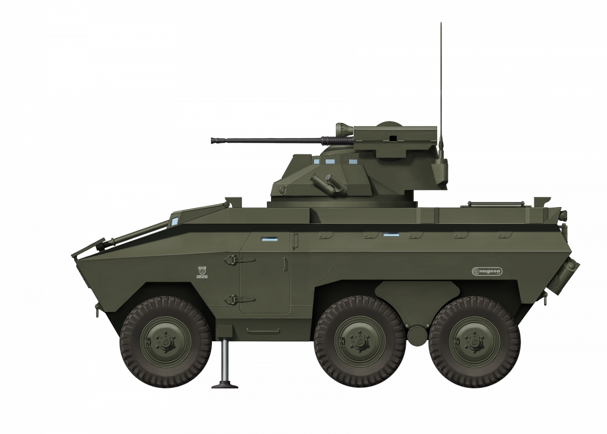
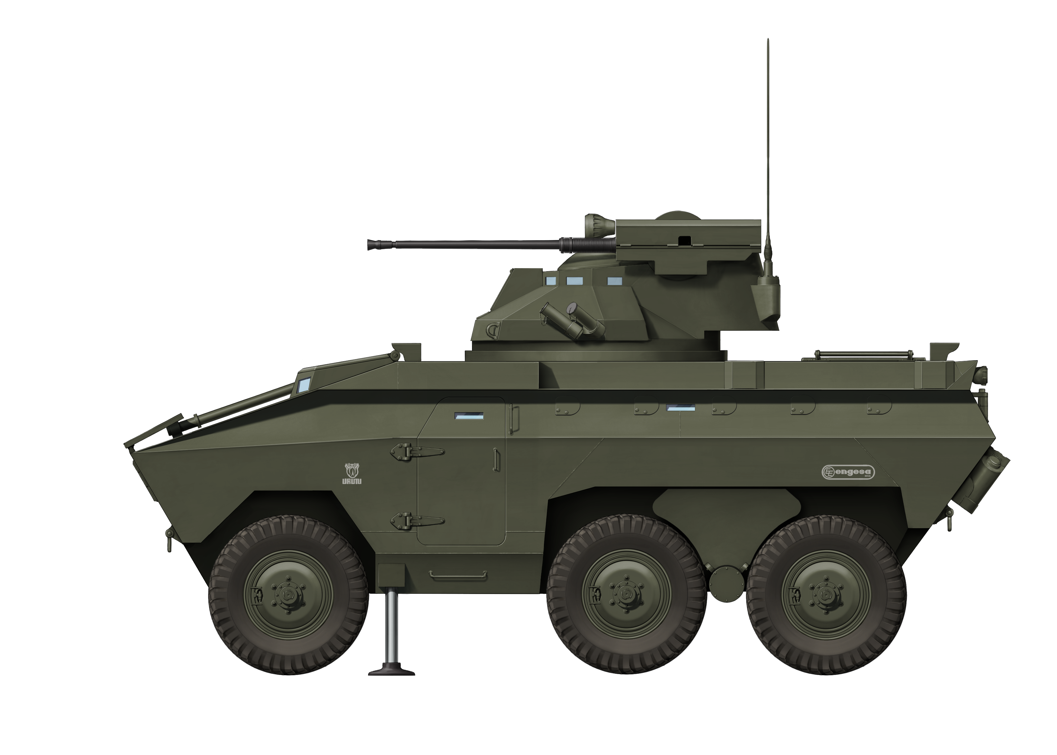
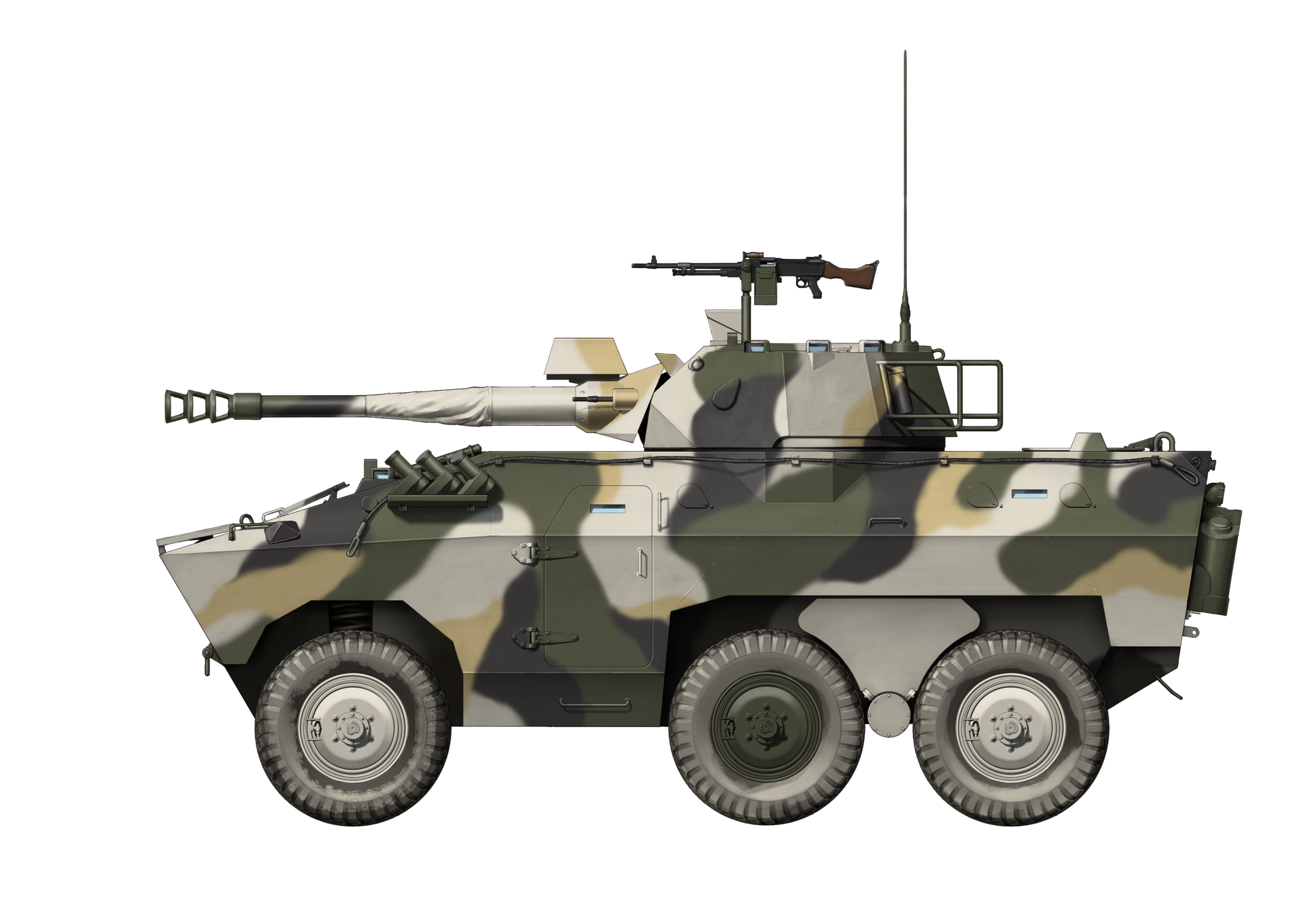
Amphibious Self-Propelled Anti-Aircraft Gun – 1 Prototype Built
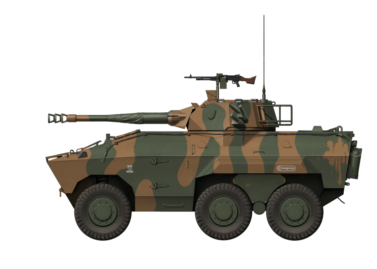
The idea of creating various combat versions for wheeled troop carriers like the Urutu was not a novel idea. In fact, it was common practice for many companies around the globe, and Engesa was no different. Since there were already a good number of countries that had the EE-11 Urutu in service, creating different versions made sense financially. The Urutu is a multiplatform vehicle that can support different types of systems/modules, from troop carrier to an anti-aircraft modification, with each one having its own purpose.

Source: Engesa brochure
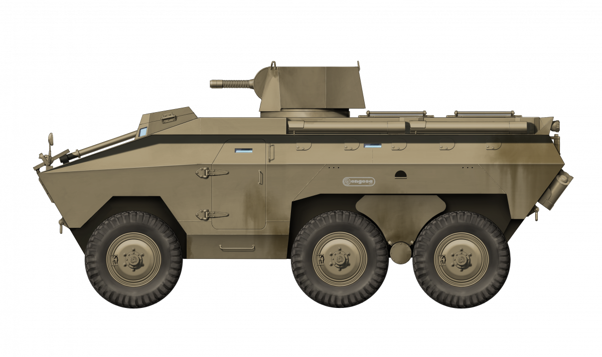
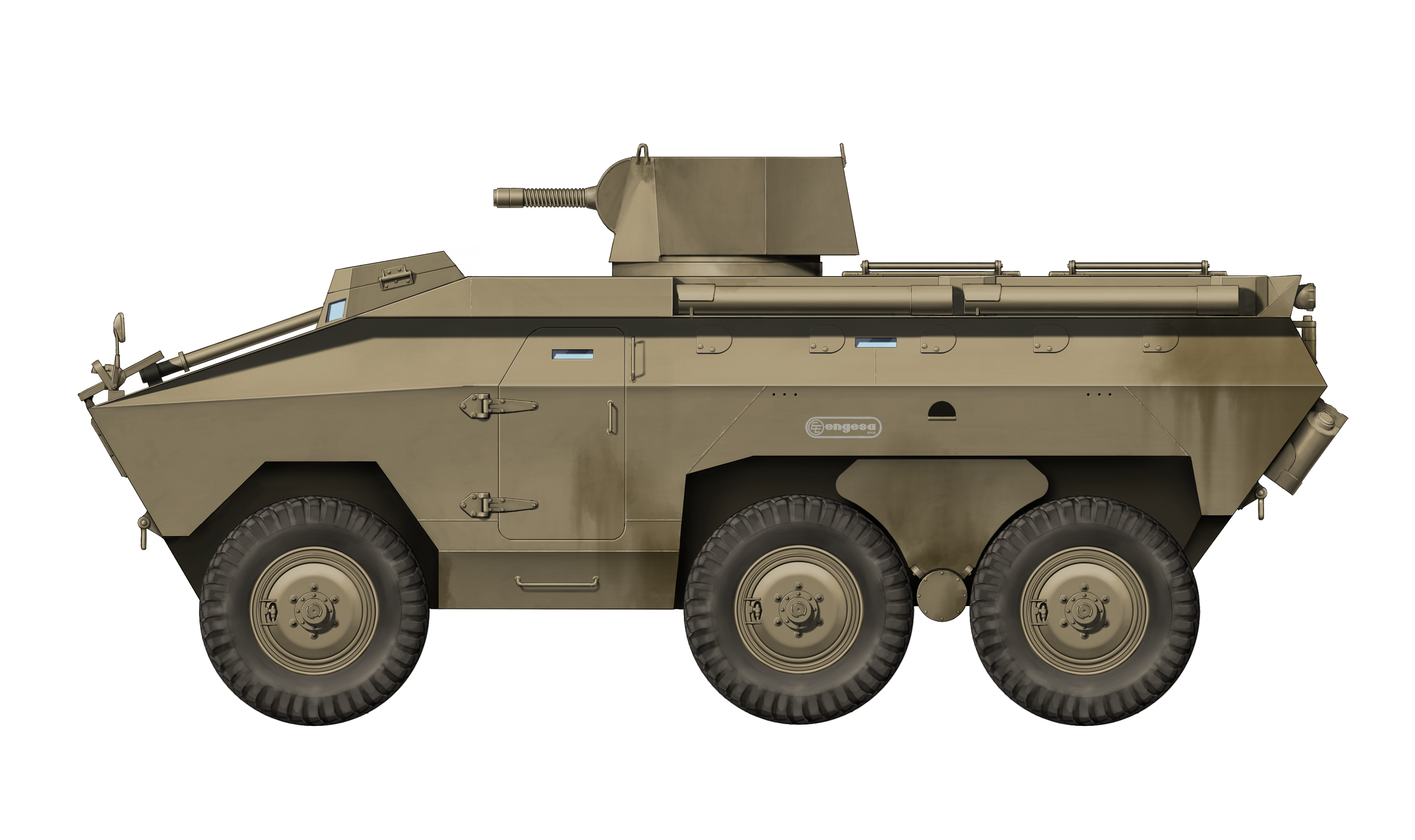
The Urutu
The Urutu was Engesa’s armored troop transport, designed in collaboration with the Brazilian Navy. The vehicle was designed from the ground up to be amphibious, and was approved in 1972 after successful testing in various conditions including open sea, for which it was modified with multiple snorkels, propellers, and a wave breaker.
Pre-production began in 1973, using the same Boomerang suspension, engine, and transmission as the EE-9 Cascavel. This vehicle managed to achieve large sales in Iraq, Libya, and most of South America, but the Urutu would never reach the same success as the Cascavel. Both the Cascavel and Urutu were upgraded throughout their production runs with different engines, transmissions, and brakes, as well as different hull designs. The Urutu was operated by a driver and commander, and could carry 10+2 fully equipped infantrymen.
In addition, it could be equipped with a multitude of different turrets, including a redesigned Cascavel turret. The Anti-Aircraft Urutu was made by mounting a twin 20 mm autocannon armed turret with a radar on the hull. Apart from the turrets, the Urutu could also receive various optional components, like an automatic fire suppression system, amphibious equipment, and Nuclear Biological Chemical (NBC) protection, all at the client’s discretion.

Source: Angelo Meliani
The EE-11 Urutu Anti-Aircraft Concept
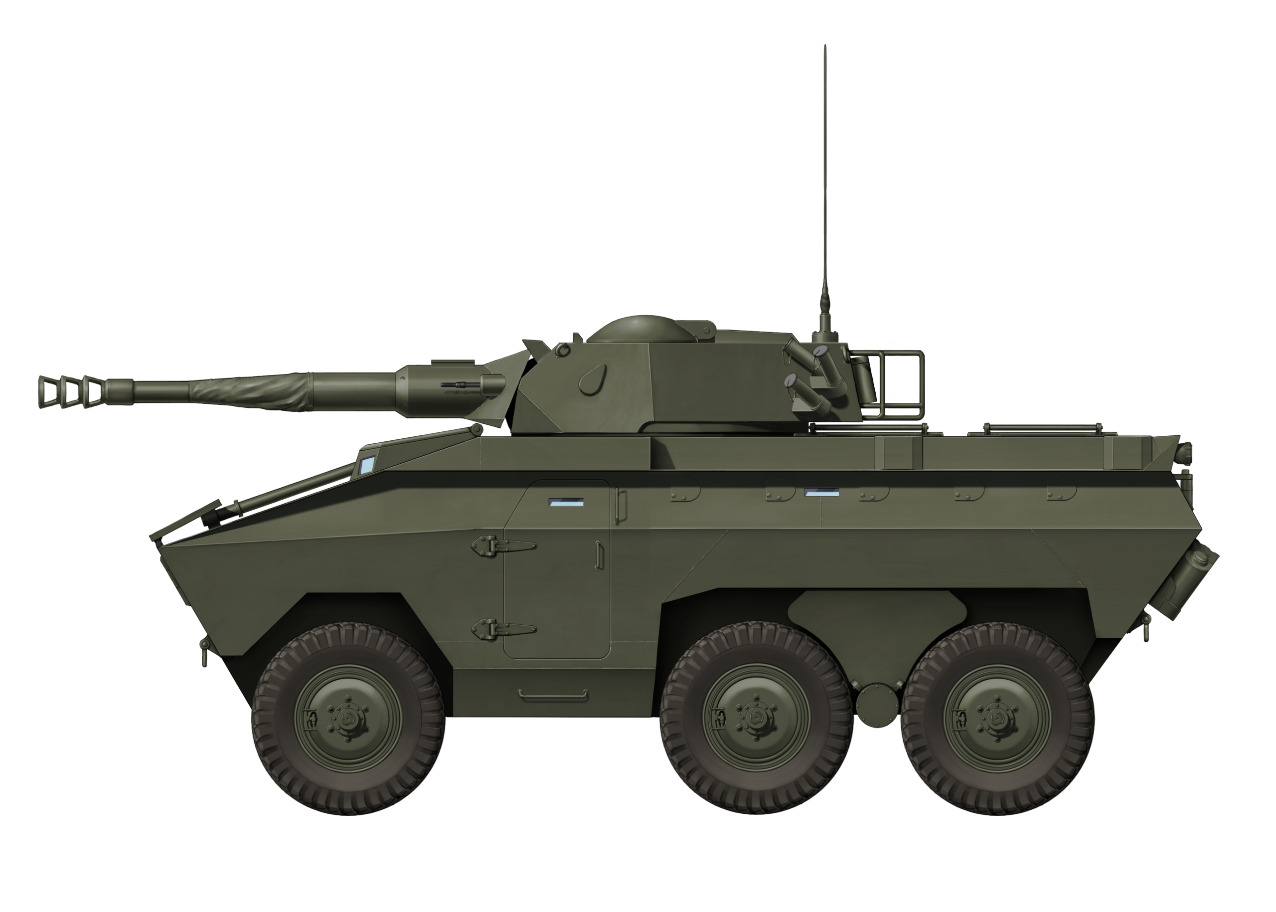
The concept of an Anti-Aircraft Urutu was already considered as early as around 1973 to 1974, when the Urutu was still in its pre-production stage. The concept would then disappear in early EE-11 M2 production model brochures. At some point between 1976 and 1980, a prototype was built on top of a slightly modified EE-11 Urutu M2 hull. This date is estimated as the M2 went into production in 1976 and the Urutu Anti-Aircraft prototype appears in marketing material for the Hydracobra proposal for the United States.

Source: https://www.infodefensa.com/texto-diario/mostrar/3057639/engesa-ee-11-urutu-do-brasil-aguardando-modernizaco
The vehicle had a crew composed of 3 (driver, gunner, and commander), it was fitted with a French TA-20 turret with access to the RA-20 radar, and the crew compartment was adapted for the needed interior systems. Two external hydraulic pistons were added on each side of the vehicle to provide additional stability during firing.
Source: Engesa brochure
The Hispano-Suiza TA-20 turret was originally paired with the French Panhard M3 VDA (Véhicule de Défense Antiaérienne, Anti-Aircraft Defense Vehicle). The companies Panhard and Electronique Serge Dassault (ESD) initiated the development for an export focused anti-aircraft Panhard M3 in 1972. The AA system was to be cheap and the M3 was already fairly popular hull in the African continent.
Hispano-Suiza was contracted to design the turret and to provide the autocannons (later Oerlikon would provide the autocannons), ESD was responsible for the radar system, and Galileo provided the sights. The first prototype was completed in late 1973 after which the vehicle entered testing. The M3 VDA entered production in 1975 when 48 were sold to the United Arab Emirates.
The TA-20 was offered in two variant: a leader vehicle or a satellite vehicle. Essentially, the leader vehicle had a radar installed, while the satellite vehicle received the target information through a radio connection. This way, two vehicles could function on a single radar, reducing acquisition costs.
It is quite likely that Engesa simply wanted to offer an anti-aircraft option and that the sale of the TA-20 to the UAE convinced the company to take the French system for the Urutu. It is as such also possible that Engesa considered it could get a slice of the cake in a newly opened market of cheap AA systems in Africa, which in the end turned out not to be the case.

Source: Jane’s Land-Based Air Defence 97-98
The Hydracobra
In the late 1970s, the EE-11 Urutu was showing signs of becoming a successful product in the global market like the EE-9. So much so that in 1980, the American company Bell Aerospace-Textron had taken interest in the vehicle and acquired a license to produce the Urutu in their own factory in the US.
After obtaining the license, Bell renamed the Urutu to Hydracobra and entered the USMC LAV competition in 1980. Bell Aerospace-Textron needed a program that offered to sell variants of the EE-11 Urutu (mainly the version fitted with the 90mm Cockerill Mk3 known as the Urutu AFSV) to the US Marine Corps (USMC) with the finality of replacing their old fleet of wheeled combat vehicles.

Source: https://www.forte.jor.br/2017/05/24/blindado-urutu-da-engesa-quase-foi-produzido-nos-eua/
With this program, a marketing pamphlet was shown with different possible variants of the EE-11 Urutu in case it was accepted. In total, 6 variants were shown: the AFSV (an Urutu fitted with the 90mm Cockerill mk3), ambulance, troop carrier (standard), recovery vehicle, ATGM carrier, and the anti-aircraft version. A number of them seem to have mainly been proposed to show that the Urutu was a multi-purpose vehicle, as the initial requirements did not even call for an anti-aircraft vehicle.

Source: https://www.forte.jor.br/2017/05/24/blindado-urutu-da-engesa-quase-foi-produzido-nos-eua/
Eventually, this would be in vain, since the Urutu lost in the initial selection rounds and wasn’t even tested by the US. The US Marine Corps opted for the LAV-25, and after this, the Hydracobra project did not go ahead.
After the Hydracobra Program
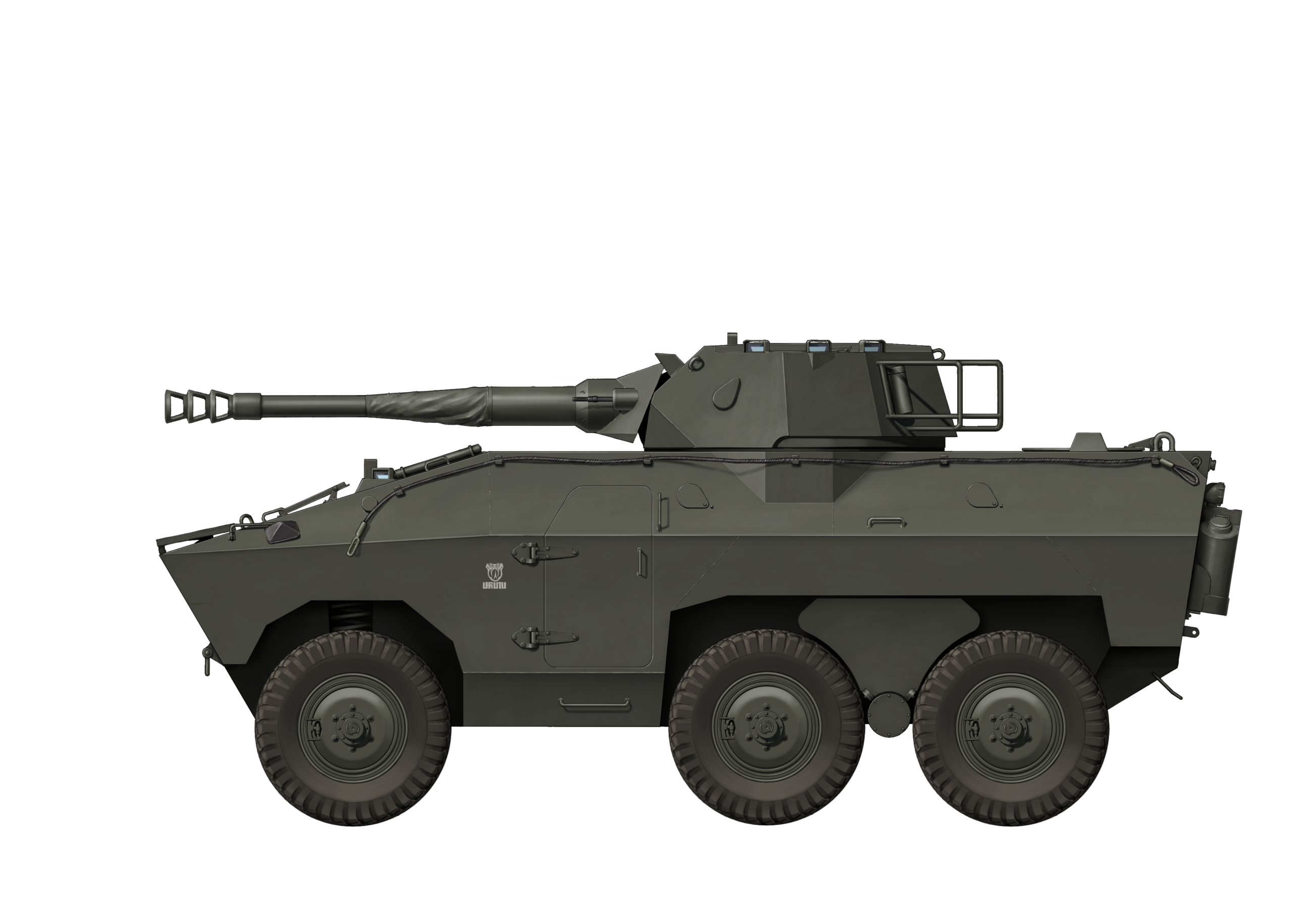
Some years after the Hydracobra program, in 1985, Engesa brochures showed that the EE-11 Urutu AA was still marketed. The brochures showed images of the vehicle and its crew layout. In addition, Engexco, the trading company of Engesa group, made a more technical-focused brochure for potential foreign operators, in which it gave more details about the vehicle and showed an EE-11 Urutu AA in a more up to date version.
The Urutu AA as offered by Engexco, was to have an MT-643 automatic transmission as opposed to the manual Clark transmission on the M2. The transmission would be paired with either an OM352A or Detroit Diesel engine. The vehicle would be offered with CTIS, could be purchased with day/night sights, and the vehicle could be used either with or without the radar depending if the vehicle was the main radar hub.
It is unknown what happened to the only EE-11 Urutu Anti-Aircraft prototype. It is likely that the prototype was either converted or scrapped.

Source: Engesa brochure
The EE-11 Urutu Anti-Aircraft in Detail
Overall dimensions were the same as the baseline Urutu, with the exception of the height and weight, due to the turret. It was 6.15 m (20.2 feet) long, 2.59 m (8.5 feet) wide, and 2.95 m (9.7 feet) tall (excluding radar, with radar unknown), which was about 0.9 m (3 feet) taller than the original Urutu. It weighed around 13 tonnes (14.3 US tons), around 1 tonnes (1.1 US tons) more than the original Urutu. This could change even further depending on the engine used. It was operated by a crew of three: commander, driver, and gunner.
Hull
The Urutu Anti-Aircraft’s hull was the same as the Urutu’s with no major difference whatsoever, except for the addition of the hydraulic stabilizing pistons and the redesigned troop compartment. That said, the choice of engine, transmissions and modifications, such as automatic fire extinguishers, were up to the client’s discretion.
The Urutu Anti-Aircraft was armored with 12 mm (0.5 inch) thick armor at the front and 6 mm (0.25 inch) on the sides and rear. It used Bimetal steel which offered an improved protection to weight ratio compared to standard steel. The Bimetal armor offered around 1.8 times the effective thickness of an equivalent homogeneous plate against 7.62 mm ammunition, meaning the Urutu had an effective homogeneous thickness of 21.6 mm (0.85 inch) at the front and 10.8 mm (0.43 inch) at the sides and rear against 7.62 mm fire.
The hull was fully welded and angled at the front and with a minor angle at the sides and rear. The rear angle varied depending on the model, with earlier models having a triangular shape, while the later models had a flat rear. The rear door was operated by the driver or manually by the passengers. All Urutus had two side doors.
The driver was positioned in the front left of the vehicle, next to the engine. The engine was located in a separate compartment. In a brochure of the Urutu, a picture is presented which shows the positions of the crew. This shows a gunner in the turret and the commander manning the radar system for the Leader vehicle (a satellite vehicle would not have the radar system). According to the Engexco brochure, the driver would support the gunner in optical target acquisition (essentially meaning the driver would open up the hatch and look at the sky) when the vehicle was stationary.

Source: Engesa brochure
The placement of the frontal headlights also varied with the hull version. Early versions had external headlights mounted on the upper front plate, while later versions had hull-integrated headlights. Attachment hooks for towing cables were present in the front, sirens could be attached to the front sides of the hull, a stowage point for a towing cable was present in the left side of the vehicle, while, on some versions, the right side was occupied by the exhaust pipe. The Urutu AA was fully amphibious, although amphibious equipment such as propellers, rudders, and snorkels were optional. A swimming vane operated by the driver was fixed to the top of the frontal hull plate.
The driver had a steering wheel to steer the vehicle, and, depending on the version, would have a brake and gas pedal to the right side of the steering wheel. The gear shift for the automatic transmission was located on his right side and the instrument panel was located on his left side. The driver had 3 periscopes at his disposal, which could be upgraded to day/night periscopes.

Source: Adriano Santiago Garcia
Mobility
The Urutu Anti-Aircraft was offered with two main engines in combination with various transmissions, although more options were possible depending on the client’s wishes.
| Engine | Fuel | Horsepower | Torque |
|---|---|---|---|
| Mercedes OM352A (turbocharged) | Diesel | 190 at 2,800 rpm | 431 Nm at 1,800 rpm (318 ft-lb) |
| Detroit DDA 6V53N | Diesel | 210 at 2,800 rpm | 598 Nm at 1,800 rpm (441 ft/lb) |
The engines were offered with a range of transmissions throughout the years in which the Urutu Anti-Air was marketed as newer variants of the Urutu were developed. From 1976 to the Hydracobra program, it would have used a manual Clark transmission with 5 forward and 1 reverse gears, and an Allison MT-643 automatic transmission with 4 forward and 1 reverse gears afterwards. Only the MT-643 could be paired with the Detroit Diesel engine. In addition, the Urutu used an Engesa 2 speed transfer case, which allowed the vehicle to be used in reduced and high gear. By putting the Urutu Anti-Aircraft in reduced gear, it sacrificed horsepower for torque, making it more effective at climbing slopes. The vehicle also offered a power take off function for the propellers through the transfer case.

Source: Blindados no Brasil – Expedito Carlos Stephani Bastos
The Urutu Anti-Aircraft had a maximum road speed of around 95 km/h and a maximum amphibious speed around 8 km/h. The Urutu Anti-Aircraft would also have had access to a remote tire pressure control system to allow pressure regulation of the tires from within the vehicle.
Its gradeability was around 60%, with the maximum side slope being 30%. The Urutu Anti-Aircraft had a ground clearance of 0.375 m (1.2 feet) and could cross a 0.6 m high vertical obstacle. It had an operational range of 850 km. It could also be airlifted, much like all other versions of the Urutu.

Source: Engesa Brochure
The vehicle was 6 x 6 driven, of which the rear 4 wheels were part of the Boomerang suspension. The Boomerang suspension, in combination with the Engesa 2 speed transfer case, would enable the Urutu to cross challenging terrain and provide maximum traction in most situations. The power of the engine was distributed to a differential on the front side of the vehicle, and a differential in the rear. The rear differential drove the Boomerang suspension with a single axle, which made the Boomerang suspension such an ingenious design.
The TA-20 Turret and Armament
The EE-11 Urutu Anti-Aircraft module adopted the French TA-20 turret that used two 20 mm H820 SL autocannons as its main armament (later Oerlikon KAD-B cannons after Oerlikon acquired the Swiss wing of Hispano-Suiza). The guns had a fire rate of 800 rounds per minute. The autocannons had access to different types of ammunitions, such as HE-I, HEI-T, APHE-I, and APIC-T. In practice, it had two ammunition magazines, each containing 300 rounds.
In addition, it had a secondary 7.5 or 7.62 mm machine gun with 200 rounds for close defense. It also had a RA-20 search and tracking radar that was installed at the rear of the turret. Each side of the turret had two smoke dischargers.

Source: http://zonwar.ru/artileru/samaxod_zenit/M3_VDA_Panhard.html
| Round | Capability | Muzzle Velocity |
|---|---|---|
| AP-T (Armor Piercing with Tracer) | 20 mm NATO standard armor angled at 45° at 800 m range | 1.150 m/s |
| HE-I (High-Explosive Incendiary) | self-destruct system operating at a range of 3 to 4 km | 1.050 m/s |
| HEI-T (High-Explosive Incendiary with Tracer) | self-destruct system operating at a range of 3 to 4 km | 1.050 m/s |
| SAPHEI (Semi Armor Piercing High Explosive Incendiary) | 12 mm NATO standard armor angled at 45° at 800 m range | 1.100 m/s |
| SAPHEI-T (Semi Armor Piercing High Explosive Incendiary with Tracer) | 1.100 m/s | |
| TP (Training Projectile) | 1.100 m/s | |
| TP-T (Training Projectile with Tracer) | 1.100 m/s |
The RA-20 Radar System
The RA-20 radar used a doubly curved reflector satellite dish which offered a beam width of 8° in azimuth and a 45° elevation. The system offered a 360° continuous rotation scan coverage with a rotational speed of 240° per second. The radar used a 400 Watt E-band frequency bandwidth which was somewhat comparable to the German Gepard‘s S-band frequency.
The system could simultaneously track two targets as standard, with the possibility of tracking up to four as optional. The target position data was automatically transferred either directly to the vehicle or through radio towards surrounding vehicles when the radar acted as the Leader vehicle for other anti-aircraft systems in the region. It could detect a Mirage type aircraft at around 9 km and an Alouette helicopter at about 7 km with an accuracy of +- 30 m and a bearing of +- mrad with an additional +-10% correction error for range and velocity.

Source: International Defence Review April 1977, page 742
Conclusion
The EE-11 Urutu Anti-Aircraft was an interesting idea from Engesa, as a cheap variant for countries that already had the standard vehicle but did not have the money to invest in more costly self-propelled anti-aircraft systems. It was fit for both helicopters and meant to be able to engage jets as well. The ability to link up Urutu’s Anti-air vehicles with a single Leader vehicle would help in saving costs as well.
The Urutu Anti-air would have been a fairly interesting option for many third world countries which already bought the standard Urutu. In the end though, it doesn’t seem anyone was interested enough in the concept. It simply seems that the French had already managed to convince the few customers available years before Engesa started offering the Urutu Anti-air, resulting in Engesa trying to get a piece of the action when the action was already over.

Specifications EE-11 Urutu Anti-aircraft |
|
|---|---|
| Dimensions (L-W-H) | 6.15 (20’) , 2.59 (8’) , 2.95 m (8’) |
| Total weight | 13 tonnes (14.3 US tons) |
| Crew | 3 (driver, gunner and commander) |
| Propulsion | Diesel Mercedes Benz OM352A-S |
| Suspension | Boomerang suspension |
| Speed (road) | Around 95 km/h (59 mph) |
| Operational range | 850 km (528 Miles) |
| Armament | 2x 20 mm H820 L cannons |
| Armor | Hull Front 12 mm (0.5 inch, Bimetal) at 70º Front (Lower Glacis) 12 mm (0.5 inch, Bimetal) at 30º Sides 8 mm (0.3 inch, Bimetal) Rear 8 mm (0.3 inch, Bimetal) at 10º Turret 8-10 mm |
| Produced | 1 Prototype |
Sources
Blindados no Brasil – Expedito Carlos Stephani Bastos
Engesa EE-9 Cascavel 40 anos de combates 1977-2017
Engesa’s Marketing Brochures
Engesa’s User and technical manuals for the Urutu and Cascavel
Research and development Title 2 – Hearings on Military Posture and H.R. 5968
LAV-25 – The Marine Corps’ Light Armored Vehicle – James D’Angina
Concept Definition and Evaluation Criteria for the Mobile Protected Weapons System and the Light Armored Vehicle – Terry A. Bresnick, Charles P. Annis, Dennis M. Buede
Kwajalein Hourglass Volume 18
Personal correspondence with Ex-Engesa employees
Engesa pretende atrair compradores para o Urutu, o Cascavel e o Jararaca – 15-3-1981
Brasil deve receber US$ 1,5 bi dos EUA por venda de tecnologia bélica – 17-4-1986
Exército norte-american poderá comprar carro blindado de Engesa – 14-11-1986
Jane’s Armour and Artillery 1985-1986
International defence review April 1977, page 742
Jane’s Land-Based Air Defence 97-98


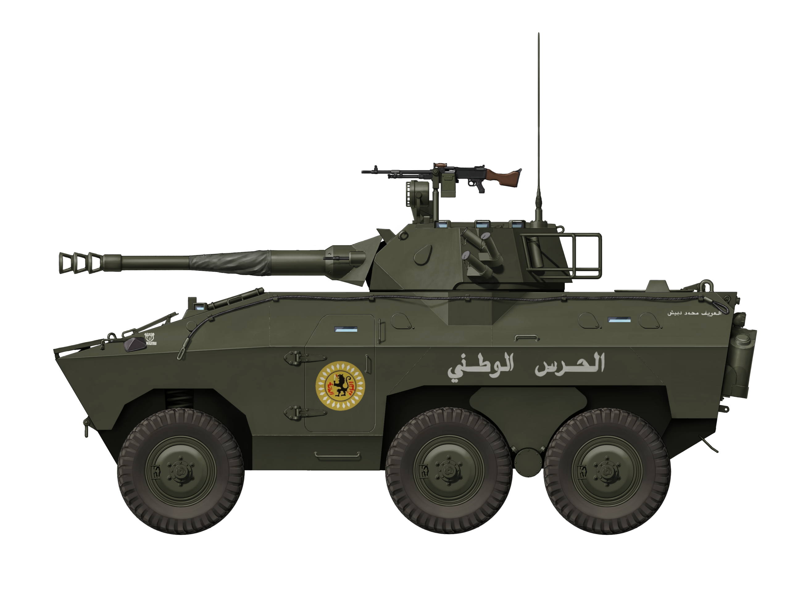
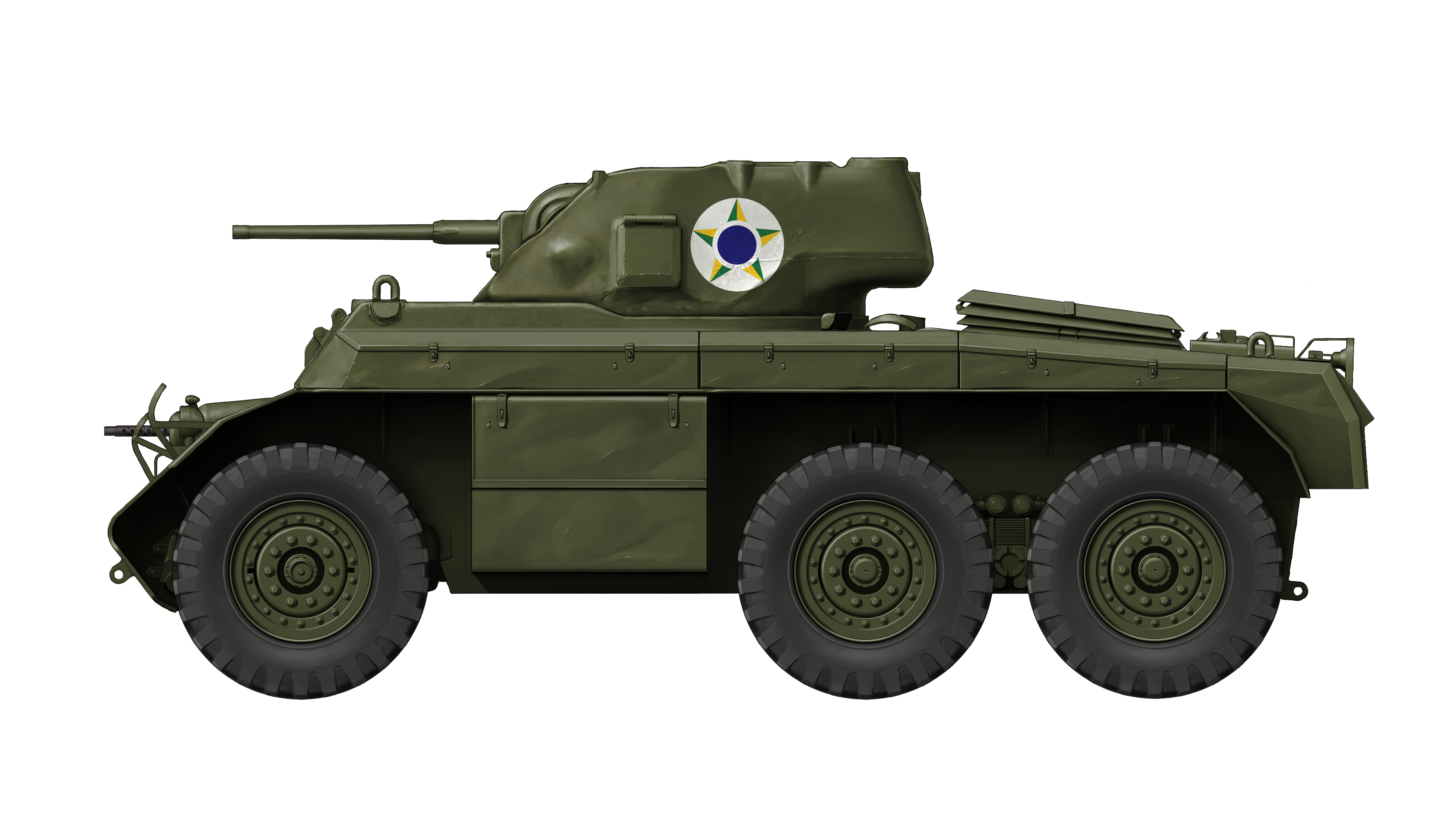
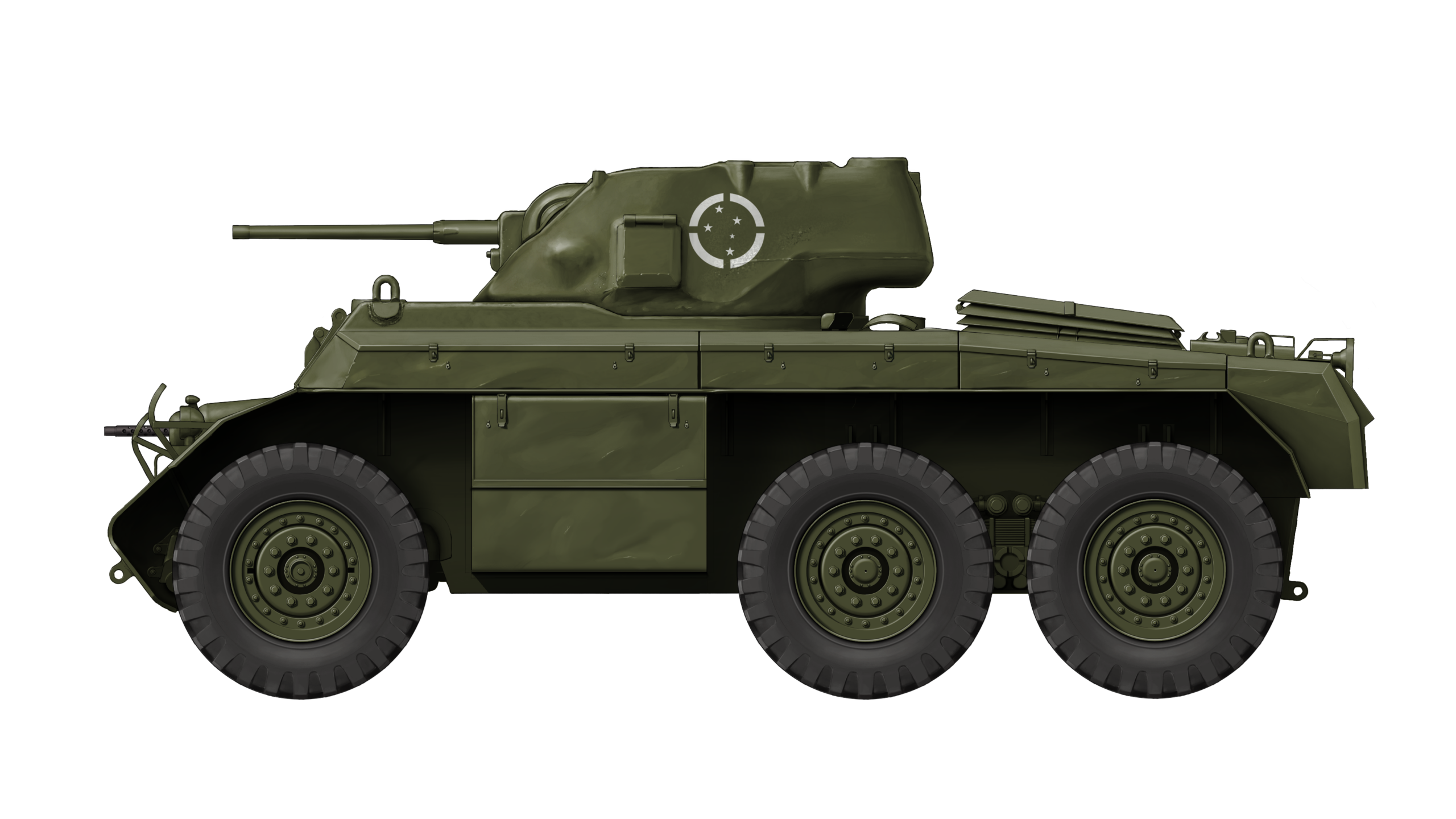
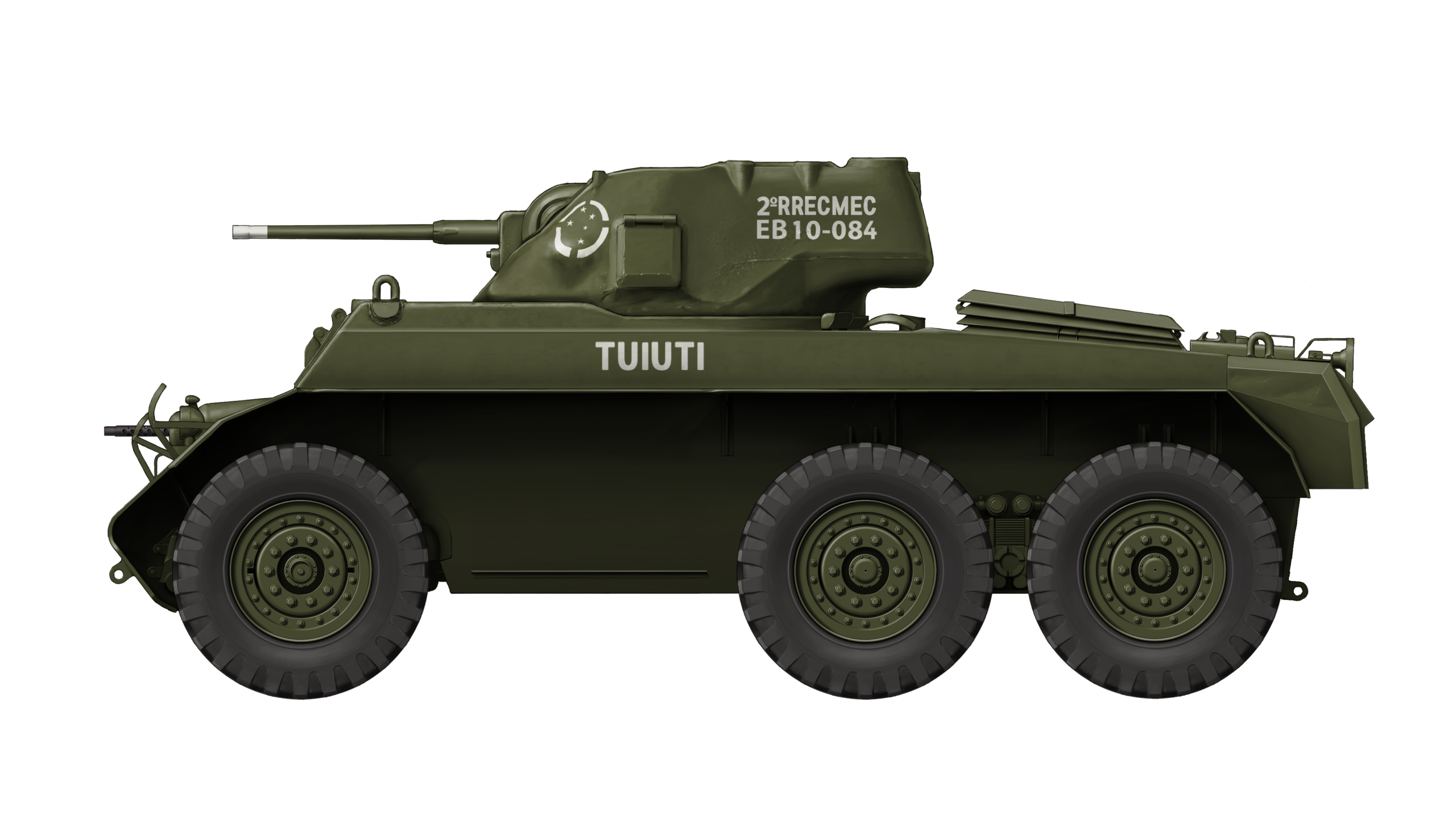
 Federative Republic of Brazil/Tunisia (1980s)


.JPG)