 France (1914-1918)
Armored Car – 4 Built
Introduction
Since its foundation in 1899 by Louis Renault and two of his brothers, the Renault company was pioneering in the rapidly growing automotive industry.
Despite rejecting the armored car concept before the Great War, French military interest in this type of weapon reappeared at the start of the war in 1914. Already in September, armored cars were planned to be used for a plethora of roles, mainly as protection against aircraft and for targeting enemy observation balloons.
Thus, the “Renault Autoblindée mle. 1914” was accepted into service and production began in the city of Lyon. It was followed the next year by the production of a Renault 2.5-tonne lorry as the basis for a 47 mm rapid firing gun, creating a vehicle that was going to be used for motorized naval infantry.
Studied after the hard experience of the fighting on open ground in the autumn of 1914 in Artois and Flanders, these powerful mobile guns were designed above all to take advantage of the useful range of the gun, of 4,500 m.

Context
When it comes to building armored cars, the French had developed two theoretical concepts before 1914. The first one was creating armored cars that were completely enclosed in armor, making them impervious to enemy small arms fire and having them equipped with turret-mounted armament. The second concept, and an opposite to this ‘fully-enclosed’ armored car’ idea was initially proposed by Captain Genty. He suggested making use of light unarmored cars putting more emphasis on speed and rapid movement while also carrying the armament on a pillar mounting. It was this second concept which initially prevailed, partially thanks to the military efforts of Captain Genty and the influence that he had.
In 1904, the army assigned Captain Genty a Panhard & Levassor 24 hp car which could be used as a reconnaissance vehicle because its high chassis enabled it to travel over rugged terrain. Its impact-resistant reinforced-wood frame gave it flexibility and solidity and it could travel at a speed of up to 70 kph. He had the idea of adding a machine gun and fitting out the vehicle accordingly. A swivel stool next to the driver allowed the gun to be fired from any position. The Panhard-Genty armored car was the first in a long line of Panhard army vehicles. Thus, in 1906, some Panhard reconnaissance vehicles were armed and were adopted by the French armed forces. By the beginning of the First World War, a handful of these vehicles were put to use.
Starting from the first weeks of the war, roughly 200 touring cars were retrofitted with armored plates and were designated according to their armament either as ‘autos-canons’ (English: cannon-armed armored car) or ‘autos-mitrailleuses’ (English: machine gun-armed armored car). None of these had a dedicated military chassis, thus the need for something more sophisticated appeared.
The concept of a lorry-mounted gun was probably first used by British Commander C. R. Samson, who mounted a 3-pounder on an L.G.O.C. ‘B’ type chassis. That vehicle was constructed for the Royal Naval Air Service (R.N.A.S.) by the French shipyard Forges et Chantiers de France at Dunkirk in October 1914. In November 1914, while the war was still raging on the Western Front, the French Army commanders began to seriously consider further mechanization. The initial success of armored vehicles (Panhard, Peugeot, and Hotchkiss models) was undoubtedly great due to their speed and their ability to be used for multiple purposes, but the ground troops lacked more powerful fire support. This led to the demand for fighting vehicles equipped with rapid-fire guns.
Thanks to General Gallieni who showed bold initiatives during 1914, many armaments could be designed and developed. This was in stark contrast to the usual passivity and fatuity of the generalissimo, barely capable of ‘conceiving armored vehicles’. In a few weeks, Gallieni, granting his confidence to enterprising soldiers and engineers, thus developing a variety of offensive armament from bombs and machine-guns, armoured trains, long-range naval components, chemical projectiles, and most importantly in this context, armored cars. The primary purpose of all these means was to harass the enemy far ahead of the entrenched camp of Paris’ (Camp retranché de Paris/CRP) fortification lines. Here they were to thwart, harass, or otherwise hinder enemy operations and to prevent the deployment of their fearsome heavy artillery in great numbers.

Development
The development for this vehicle started during 1914-1915, with several prototypes shown. The most common were those on the chassis of the Peugeot commercial trucks. However, a very successful ‘car cannon’ on a Renault chassis was produced in limited numbers. The initiator of this design was Lieutenant Villeneu-Bargemont, who in a short time, prepared a project based on a 2.5-tonne Renault truck chassis. The first prototype of the Autocanon de 47 mm Renault was presented on 15th August 1915. Its performance during tests was quite encouraging, but, by this time, both warring sides were firmly entrenched, and the use of road-bound vehicles like these was proving difficult under the new circumstances. Adapting to the changed situation, no large order was placed for cannon-armed vehicles of this type. Apart from the prototype, three other serial machines were built. They were sent to the front and used repeatedly until November 1918.
The first assembly of a 47 mm gun model 1885 on a so-called ‘automatic recoil mount’ is made on the chassis of a 3-ton Renault EP truck, probably on direct order of the CRP dating from September 1914.

The equipment was studied by Renault with Lieutenant Hergault. The pedestal was bolted on the platform of the truck which rests directly on the vehicle tyres. The first tests took place at Satory, near Versailles on 12th October 1914 in the presence of General Clergerie, Gallieni’s Chief of Staff. Here, some 30 shots were fired at a range of 1,200 m within the limits of the firing range. It turned out that these shots were very accurate and that the automobile chassis withstood the recoil forces from the gun whilst firing in all directions. However, the assembly was found to lack stability and the gun mounted on its pedestal to be too high compared to the platform. A note from 16th October 1914, proposed the deployment of 47 mm naval guns in the flat regions of Northern France. This would allow for better long-range engagements against enemy troops (up to 4,500 m). The approval for such projects was given on the 18th November by General Gallieni.
This equipment nevertheless appears all the more interesting to General Louis de Maud’Huy, commander of the 10th Army, who pointed out that the Autocanon recently put into service could be used for firing against aircraft since they were very capable as support weapons. Their capabilities could be improved in terms of firepower by ‘substituting 47 mm guns for 37 mm guns’. At that time, the Minister of War announced the existence of 90 quick-firing 47 mm guns, taken from coastal defenses and supplied with 500 rounds.
At the end of October 1914, General Gallieni had twelve of these 47 mm guns at the Grand-Palais; he suggested using this equipment for anti-aircraft fire on the automobile platform studied by Renault. All these suggestions initially remained unanswered, since the Vincennes park (French: Parc de Vincennes) reported on 21st December that the “ninety-two 47 mm guns in storage had not been used either by the ground forces, the air force or the armored cars”. The park only had 17 mountings for this equipment, ten of which have two recoil buffers, and seven have only one recoil buffer. It is certain that the automatic recoil mount was more suitable for mounting on a car chassis, to absorb the recoil of the 47 mm gun as much as possible.
However, after reflection, the Minister of War decided in November 1914, to entrust the military government of Paris to experiment with the construction and organization of four armed cars and a supply car, the vehicles would be crewed by naval personnel thus naval instructors for the usage of the armaments were also needed. The studies were coordinated by Lieutenant-Colonel Cordier, Commander of the Grand Parc Automobile de Réserve reserve fleet (GPAR) in Vincennes, in liaison with the manufacturer Renault and Captain Renaud. It was agreed to reduce the height of the piece in relation to the platform by placing the gun on a centrally rotating carriage, with a low support, requiring the gunner to fire in a kneeling position. The front of the chassis, the engine, and the radiator, were fully armored.

The construction, initially planned within 25 days after receiving the order, was delayed, especially as contradictory discussions began about the use of these 47s. General Gallieni wanted two 47s to be assigned to each of the 15 groups of the existing 37 Autocanon, thus implying the construction of 30 machines.
The Governor of Paris was also considering assigning two 47s to the 14th and 15th Groups and them as soon as the four pieces of equipment ordered ‘as an experiment’ were completed. As was to be expected, the Minister’s response, after consulting General Joffre for his opinion, was negative. The Minister did not authorize any new construction of the 47 Autocanon because the General in charge considered that there would be a disadvantage in bringing together 37 and 47 guns within the same group, for logistical and practical reasons.
In these conditions, the future of the four 47 mm Autocanon built became uncertain, especially as the users’ reports underlined the defects of the equipment. Ensign Pouyer, Commander of the 47 Autocanon section since 1st February 1915, was very critical of the equipment. The main defect he noted was the prohibitive weight of the Autocanon, which reached 6,500 kg, and the underpowering of the truck. This led the manufacturer to make its engines run 200 revolutions faster than their normal speed, i.e. 1,300 revolutions/minute instead of 1,100, by tampering with the regulator. Moreover, the wheelbase of 3.85 m made maneuvers difficult, especially with the large rear overhang which brought the length of the vehicle to 5.80 m.
Ensign Pouyer, taking into account the experience of the battle of the Autocanon in Belgium, feared that the 47’s equipment could not maneuver on the narrow roads of Flanders and that traversing in order to hide from enemy fire was particularly difficult. On 8th March 1915, he reported on the very difficult march of the two 47s to Fontainebleau five days earlier from Billancourt with two 37s and two Saurer trucks, one of which carried a 75 mm gun, to carry out firing tests.
During the first 27 kilometers, the 47s were outpaced by the other vehicles and were dragging themselves along at an average speed of 12 km/h. The Renault drivers had to remove their regulators, even though they were set at 1,400 rpm, which allowed them to drive the last 36 kilometers at an average speed of 22.5 km/h, at the cost of engine fatigue and high radiator water temperature. On the other hand, the shots fired at Fontainebleau – 46 shots per piece at distances varying from 2,100 to 2,300 m showed the equipment’s ability to fire accurately in all directions, with the exception towards the front. During the return march to Billancourt, the drivers pushed the Autocanons to more than 50 km/h (instantaneous speed) at 3,700 rpm. During tests undertaken at Renault on 5th March, it appeared that the speed with the regulator set at 1600 rpm could not in practice exceed 20 km/h. In these conditions, the dispatch to the armies was postponed, which left time to define exactly the composition of the unit.

It is also worth mentioning that four armored Autocanons were made into one ‘Groupe’ which will later be referred to the 1st Group while there was a second Group of Autocanons which was composed of the same vehicles but these were completely unarmored. This second group also had 4 armed vehicles but alongside it was also operating two 47 mm guns on mounts that were deployed on the ground and not on vehicles. They were also deployed alongside the 1st Group for anti-air purposes at the entrenched camp of Paris (CRP). After some studies, it was decided by the ministry that both the 1st and 2nd Group would be moved to the positions betweenDammartin and Le Plessis-Belleville in northern France.

Design
Overall Design
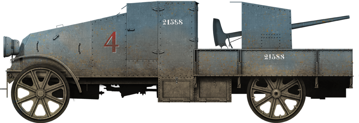
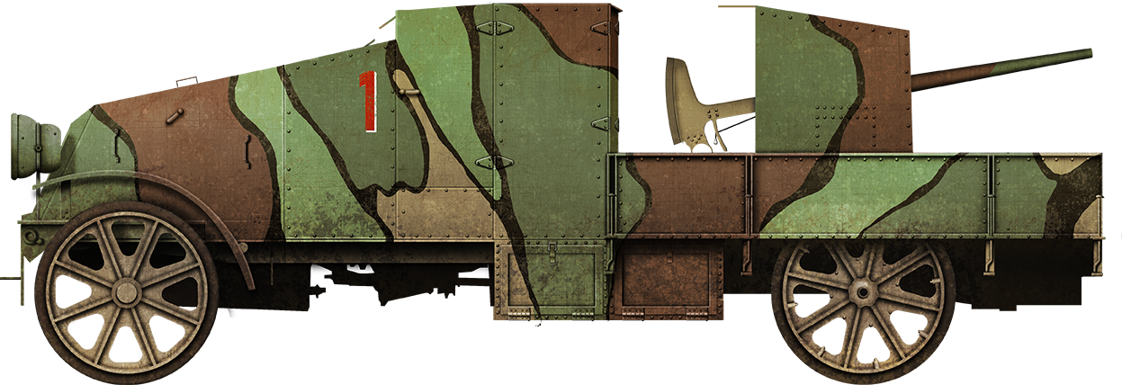
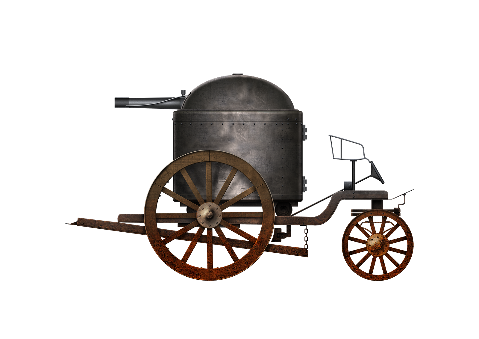
The vehicle was intended to be used for direct fire support for the infantry on the battlefield, thus crew protection was going to be needed. The driver’s cab and bonnet were fully armored, with the top armor plates installed at a steep angle. The armor was made from 7 mm thick plates that were supplied from Saint-Chamond, probably by the manufacturer “Compagnie des forges et aciéries de la marine et d’Homécourt” (FCM) (English: Company of marine forges and steelworks and of Homécourt). The armored Autocanon of the 1st Group were equipped with the 47 mm gun model 1885 mounted on a so-called automatic recoil mount, with two side recuperators, on a special type of support, most probably using components of the regulation mount model 1887, modified to reduce the height of the trunnion axis.
The mounts were then fitted with a fork-shaped mount known as the Fauconneau (a ‘Fauconneau’ was a small type of medieval cannon), allowing shooting against aircraft up to 70 degree angle. At least for a while (spring 1917 according to photographs), the Autocanon “1” kept the primitive mount, intended mainly for firing at full tilt up to 13 degree while the other three “2”, “3” and “4” were equipped with the Fauconneau mount. While the 2nd Group was equipped with the 47 mm model 1885 with a great diversity of mountings. For the first section created (on standard Renault EP standard), one Autocanon was equipped with the automatic recoil mount model 1887 with support and the other with the recoilless mount with support like the one used with coastal artillery and on certain small old ships of the navy. The latter, whose recoil is more violent on an automobile platform, received later, a Fauconneau mount to improve the conditions of the shooting against aircraft. At an unknown date, the two of the vehicles received a shortened support base (shaped like a chandelier-like structure) intended to decrease the shocks of the shooting by decreasing the height of the piece compared to the automobile platform.

To improve the protection of the gun crew on the armored vehicles of the 1st Group, the gun mount was protected by a U-shaped armor plate with a roof. The traverse was about 270 degrees, and the ammunition was stowed in a compartment behind the driver’s cab. The gun was mounted low between the rear wheel arches in the body of the vehicle. The only disadvantage of this lower mounting was that the gun did not have a forward field of fire, because the driver’s cab was in the way. The first prototypes were completed by the end of January 1915. Tests showed that the heavily armored vehicle was too heavy, and the speed too slow, and no more than four were manufactured.

Armament
The armament that was chosen for the vehicle was the Hotchkiss 47 mm model 1885. The specific model was chosen because it had more than double the range of the alternative, the 37 mm that was produced by Hotchkiss. It was designed and manufactured by Hotchkiss et Cie (French: Société Anonyme des Anciens Établissements Hotchkiss et Compagnie). The weapon was used in three different types with the main difference between them being the height of the trunnion axis and the weight of the mount. The most common type of ammunition that was fired from this gun were steel (model 1892 and 1911) and lyddite. The steel shells (not to be confused with cast iron shells) were very similar to the British common pointed shells, since they were also filled with gunpowder and a base percussion fuze. The only difference between the two was that the tip of the shell resembled a British AP (armor-piercing) shell. The latter meant that the body of the projectile held less powder and the solid section (penetrator) was longer. Similarly to the gun itself, the ammunition was also designed for naval use. The Lyddite (equivalent in French ‘melinite’) shells were the first form of high explosive shells, using the shrapnel they created after they exploded to cause damage to the surrounding area in order to maximize the destructive capability of the shell. A delayed fuze was needed until the shell had penetrated its target. Other shell types included cast iron shells (model 1892 and 1902) and canister shot (model 1886) containing 76 steel balls weighing 17 gr each.

The armament with the initial mount was able to achieve a depression of just +13 degrees while the ones equipped with the much better Fauconneau were able to achieve +70 degrees. It is also worth mentioning that there were some minor variations between the gun with the difference being between the weight and the length of the trunnions.

 Diagrams of the cannon barrel(Top) and some of the shells that the gun was able to fire.
From left to right
-
- Steel shells mode l1888
-
- Cast iron shells model 1888
-
- Canister for grapeshot model 1886
-
- Complete cartridges of 47 mm
-
- Cartridges with cast iron shells model 1885
Source:Histoire de guerre, blindés & matériel No.113
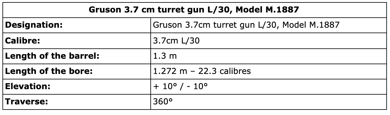
| Gun table of data | |
|---|---|
| Designation | Hotchkiss 47 mm M1885 |
| Caliber | 47 mm |
| Weight of the barrel | 237 kg |
| Weight of mount | 380-538 kg |
| Barrel length | 2.35 m |
| Muzzle velocity | 600-610 m/s |
| Elevation | +13°, -10°/ +70° , -10° |
Mobility
The drivetrain was a 4×2, with spoke wheels with rubber tires. The vehicle featured a leaf-spring suspension which, due to the nature of this type of suspension, allowed for better vertical weight handling and distribution. Leaf-springs had much better response time after a vertical flex in the suspension, thus making for a much more controllable car. A 16 hp 4-cycle Renault petrol engine was placed under the bonnet, which was clearly insufficient for a heavy vehicle, giving the armored car a top speed of roughly 20 km/h and a 5 hp/tonne power to weight ratio.
Operation/Service
These Autocanon were manned by naval personnel ‘Fusiliers Marins’ and were ready for action, organized in sections of two, in June 1915. Each vehicle was manned by a crew of 4 (commander, driver, gunner, and loader). They seem to have been mainly used as anti-aircraft operations, but were also used as mobile light artillery, moving along the lines, attacking any targets when an opportunity arose. The First Autocanon Group was equipped with the only four vehicles that were produced and they were also given four machine gun cars from the same manufacturer. The Group was placed near Dunkirk.
The 1st Group of 47s of the Navy in Flanders
At the end of its laborious tests and after a request from General Foch, the group of ’47 Autocanons set off on 15th June 1915 from Paris to Dunkirk, in four stages at Beauvais, Amiens, and Thérouanne. It is likely that its commander was able to pass on a message to General Foch’s staff, about the lack of a telemeter or a telemetric binocular, since General Weygand, Chief of Staff of the Northern Army Group, GAN), asked the Navy to supply a Barr and Stroud rangefinder, on the grounds that the Autocanons were to be used especially for firing against aircraft.
- Τhe group was given three types of missions:
Defense against aircraft, even though the low vertical depression of the 47 mm guns did not initially allow for optimum performance. - Defense of the North Sea coasts; indeed,despite the superiority of the Allied fleets, incursions on the coastline were still to be feared, especially behind the lines of the Nieuport front. As a result, many station points guarding the seafront were defended on the coastline.
- Finally harassment and destruction of the enemy front line defensive works by taking advantage of the accuracy and range of the 47’s cannon.The way that the Autocanon would achieve that was by quickly occupying suitable firing positions ,fire against enemy fortifications and then withdraw to avoid enemy reactions.
In the latter role, the 47s were to be of great service when they were placed at the disposal of the Nieuport group in the autumn of 1915. This sector was then occupied by the 38th Division, whose Commander, General Rouquerol, was keen to keep the enemy on his toes. By making excessive use of artillery and Autocanons to increase the number of local attacks by his troops.
The 1st Autocanon Group took part in the following operations:
- On the 5th of November 1915, a section of two 47 mm Autocanon fired 160 shells on the southern flank of the Grande Dune of Nieuport.
- On 22nd November, traveling on the Nieuport-Ville – Nieuport-Bains road, the Autocanon destroyed two forts on the coast with 150 projectiles.
- On 27th December, 10th and 26th January, and 8th February 1916, shots were fired at the Grande Dune.
- On 17th January, shots were fired at the Groote-Bamburg work.
- On 6th April, shots were fired at the roads and crossroads north of Lombartzyde
- On 23rd March, and 3rd and 22nd May 1916, the defensive works of the Villa Crombez were heavily shelled, particularly on the last day when 598 rounds of 47 mm ammunition were fired.
In the service of the Navy
There is no doubt that in the conditions of trench warfare, the Autocanon provided more service than the regular stationary guns. General Rouquerol regretted the departure of the 1st Group of 47 Autocanon of the navy, ordered by the GQG (Grand Quartier Général) on 22nd May 1916. In fact, in order to meet the demands of submarine warfare, at the beginning of 1916 the naval staff requested the recall of all its personnel employed at the front, with the exception of the marine gunners and some specialist units. Lieutenant de Villeneuve-Bargemon, supported by Commander Goybet, inspector of the navy’s Autocanon groups, pleaded for the maintenance of his unit since they could not trust cavalry or infantry men to operate properly the weaponry of the AC. The conduct of indirect fire with the naval cannons required knowledge and practice that his crews possessed and he needed to keep this knowledge. On 26th May 1916, General Rouquerol greeted with emotion the departure of the 47 navy Autocanon group and more particularly that of the navy officers and pointers, thus underlining the value of these personnel. The navy group was officially disbanded on 31st May 1916.

Defense against the tanks
After the failure of the spring 1917 offensives, the 1st Group was used essentially for flak on the 6th Army’s rear and a new mission was added to the previous one. Indeed, since the end of 1916, the GQG feared that the enemy would build and use tanks in turn, as concordant intelligence tends to indicate.
In these circumstances, the 1st Gun Group could play an important role defending against tanks. General Franchet d’Espérey, commanding the North Army Group, considered in July 1917 that the 1st Group of 47s should be used for flak against low-flying aircraft during the stabilization period and, during active operations, as ‘road tanks’ from a stationary point involving relatively little movement. By the end of August 1917, the group was defending the town and station of Villers-Cotteréts, but its situation was soon to change once again.
On 4th January 1918, both the 1st and the 2nd Group of AC were ordered to move to the Trilport – Isle-les-Meldeuses line, a major railway junction. The first big night raid of the German air force on Paris took place during the night of 30th to 31st January. The 47s fired no less than 986 shells that night. A supply of 2,000 rounds was then provided for the Autocanon alone and orders were given to deliver 360 explosive shells to them so that they would be in a position to give possible assistance to the ground defense of the CRP. On 8th March 1918, another major German air raid passed over their positions; they fired 1,800 shells during the night. In these conditions, the Ministry of Armament was asked to manufacture 14,000 47 mm shells in order to maintain the group’s initial supply of 500 rounds per piece and to build up a reserve of at least 10,000 rounds. The great German offensives of spring were accompanied by the continuation of the campaign of night bombardment of Paris and its region by the Gotha bombers, Friedrichshafen, and the giant Riesenflugzeuge planes.

From the end of May 1918, the enemy planes encountered a powerful flak in the north and east of the Parisian agglomeration. From then on, the black cross bombers tried to bypass Paris by the south and to reach the heart of the capital by the region of Corbeil – Villeneuve-Saint-Georges. In the summer, the evolution of the military situation forced the German air force to give up attacking the capital where the last raid was recorded on the night of the 15th/16th September 1918. The 47s were then out of breath and had no further opportunity to engage the enemy. The signing of the armistice led to the rapid demobilization of many anti-air units, essentially composed of old and wounded personnel who were unfit for service at the front. In February 1919, The 21st Gun Group to which the 47 AC were attached was transferred to Arnouville for disbandment. The final fate of the equipment is not precisely known.

Conclusion
Even though the Autocanon de 47 mm Renault was used in a role that was not very well covered by other military means during the First World War (mobile infantry support / anti-air) its overall design was lackluster and it was technically unsound. The drastic change in the way the war was fought led to a more static battlefield, which was completely ill-suited for mobile armored cars. This meant that the Autocanon had to rove up and down the battlefield looking for targets, peek up, fire and quickly get out to avoid retribution. This only exacerbated the fact that the vehicle was already considered slow, thus resulting in its overall replacement by other armored cars that were better designed for their respective roles.

| Autocanon de 47 Renault mle 1915 Specifications | |
|---|---|
| Dimensions | Length: 4.7 m Width: 1.7 m Height: 1.7 m |
| Crew | 4 |
| Propulsion | 16 hp 4-cycle Renault petrol engine |
| Suspension | Leaf-Spring |
| Armament | Hotchkiss 47 mm L/50 M1902 |
| Armor | 7 mm thick armor plates |
| Production | 4 |
Sources
http://www.landships.info/landships/car_articles.html?load=car_articles/Renault_Mle1914.html#
https://weaponsandwarfare.files.wordpress.com/2018/06/asdsdca.jpg
Early Armoured Cars (Shire Albums) by E. Bartholomew ISBN 10: 0852639082
Histoire de guerre, blindés & matériel No.113
https://www.arquus-defense.com/captain-gentys-panhard-armored-car-arrives-morocco
https://wikimaginot.eu/V70_glossaire_detail.php?id=1000280

 Republic of Cyprus (1963-1964)


