 United Kingdom (1916)
Heavy Tank – Design Only
Tanks, the new wonder weapons of mechanical inspiration, armored leviathans running on steel tracks to smash their way through German positions on the Western Front, were first used at the Battle of Flers-Courcelette on 15th September 1916. Straight afterward, rumors of this new weapon started to circulate amongst the Central Powers and in the minds of the general public in Britain, France, and elsewhere. Nonetheless, the first public airing of a photograph of a tank did not get published until 22nd November that year. Yet, although the idea of an armored mechanical war weapon was not new and had appeared in both serious and some far less serious versions, including science-fiction stories beforehand, this was not the first use and first publicity which had the tank or ‘landship’ seize the imagination of the home front. It is then perhaps ironic or just coincidentally timed that Percy William Atherton, a London-based engineer, submitted a completely independent design for a giant wheeled land machine clad in armor and fitted with turrets exactly one week prior to the action at Flers Courcelette.
The Man
Percy William Atherton is not a well-known name in tank design or military circles. Indeed, he is elusive in the historical record save for a patent filed in November 1900 for an improved type of rim for pneumatic tires.
At the time of filing an application for that patent, he was already engaged as an engineer by profession and provided an address on Tenison Street, York Road, London – an area of the Southbank just north of Waterloo Railway Station.
In 1901, still with the address at Tenison Street, he filed another patent, this time for gloves or mittens which allowed their finger and/or thumb to be exposed without taking them off. He was now providing his occupation as a consulting engineer.

In 1908, Atherton revealed that he was obviously doing reasonably well financially, as he was the owner of a 3 cylinder 12 hp Clyde motor car (Clyde Motor Company Ltd. Leicester) and managed to entangle himself in an argument in a contemporary periodical over opinions on the reliability of the aforementioned brand of vehicle. Other than this, all that can be deduced at this time is that sometime between 1908 and 1916, he took a contract to work in British India as an engineer for the Public Works Department (P.W.D.) and was living at Shorkot Road Junction, Punjab, India – about halfway between Faisalabad and Multan in modern-day Pakistan. When, in September 1916, he gave this occupation, he also provided a UK address in Gloucester Street, Warwick Square, Westminster, London, southeast of the modern-day Victoria Coach Station.
He was also now a member of the Institute of Municipal Engineers (IMunE.), an organization which eventually (1978) merged with the Institute of Civil Engineers (I.C.E.), showing that he had continued to progress in his skills as an engineer. With a war waging in Europe and with his home nation forces stalled against a seemingly impenetrable wall of German wire and machine guns, Atherton turned his engineering skills to consider a mechanical solution to the problem.
The Design
Regardless of whatever engineering skills, training, abilities, or experiences he had by 1916, Atherton designed what has to rank as one of the most ludicrous wheeled vehicles ever proposed for any purpose – let alone military ones.
It is important to see that, whilst the wheels in themselves are ridiculous in proportion to the vehicle they are carrying, they are also ridiculous in their own right as they were to be up to 300 feet (91.4 m) in diameter. This was no armored car – it was meant as more of a wheeled warship and only half as sensible as that sounds.
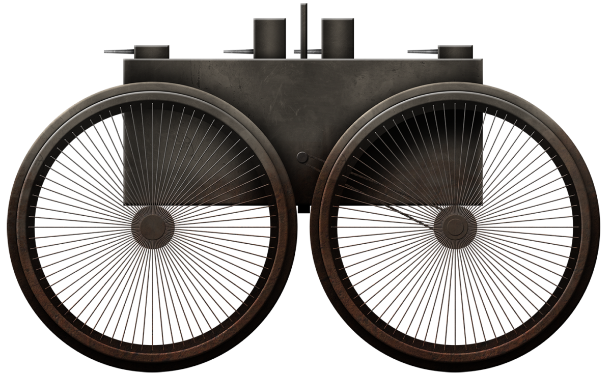
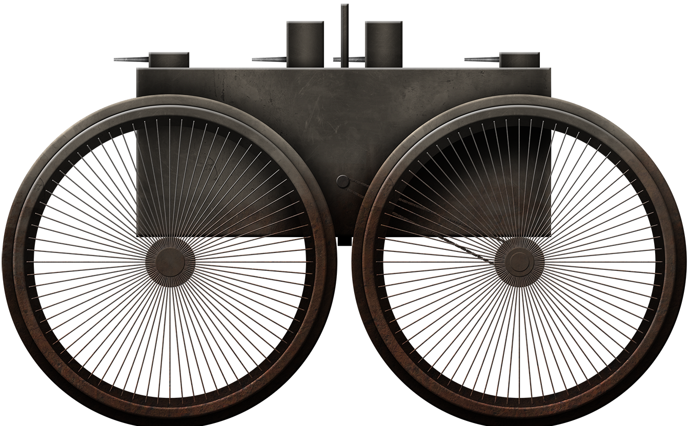
The overall premise resembled a narrow pram or pushchair with ridiculously large wheels. Instead of a baby carriage, however, Atherton proposed not much shy of a dreadnaught mounted within these wheels. He described this heavily armed body mounted in that manner with four or maybe more wheels where the body of the vehicle actually lay above the axis of rotation of the wheels.
The body itself was essentially rectangular with a rounded front and rear and topped with turrets. The motive power driving the vehicle was pictured as being fairly rudimentary, with a clearly drawn drive belt or chain running from the center point on each side of the body to the rear axle.


Inside the hull, there were to be several floors (decks), with the primary magazine located in the center for protection and surrounded by drinking water tanks and hydraulic equipment. The drinking water served both to provide fresh water for the crew but also allowed the magazine to be flooded, just like on a warship, to prevent an explosion.
Armament
Atherton’s fort, in the tradition of the amateur inventor, was to be excessively well-armed, mounting no less than four turrets along with the heaviest possible guns – the sort normally fitted into fixed concrete mountings. These were to be complemented by an array of guns of other smaller calibers, and a slew of Maxim-type machine guns, as may be deemed necessary. He did not specify what size these guns were to be, but four turrets are clearly shown in the plan view with a pair of large guns each, for a total of 8. These guns would have been large, not only because of the scale at which they are drawn in relation to the massive vehicle but also because he carefully noted the use of hydraulic or other equipment to assist in the loading of the ammunition. Clearly, Atherton had some level of knowledge of loading large guns, presumably of a naval nature, but he also quite evidently had zero practical understanding of not only the issues of command and control over such a plethora of weapons but also the limitation of them.
He had made an obvious and conscious effort to avoid the turrets interfering with each other so that the gun turrets being rotated could not accidentally strike another turret, yet the central two turrets are close enough that they could, in theory, have clashed barrels if, for whatever reason, the leading central turret was rotated all the way to the rear. As shown in the side view by Atherton, although turrets 1 and 4 (front and rear, respectively) are positioned along the longitudinal axis of the hull, turrets 2 and 3 (the central pair) are offset to the left and right respectively. This is unlikely to be a mistake on such a simple drawing and is more likely to be an attempt to allow the guns to fire past each other to the front without causing interference. However, as each turret was more than half the width of the body, this was still not possible.
One final note on the turret size and position is that turrets 1 and 4 are clearly shorter than numbers 2 and 3, in what might be assumed was an attempt to allow the central turrets to fire over the top of them. However, the low position of the guns in all four turrets, as illustrated in the side elevation of the design, would preclude this and the purpose of the central turrets being taller is therefore unclear.
Atherton was vague on the turrets when he described that they may be arranged so as to deliver fire close to the machine. This presumably would require some turrets underneath for that purpose. He did mention, however, that a second battery of guns could be fitted at the ends and/or along the sides of the hull to provide fire at up to -45 degrees, although this would still leave a large dead zone directly underneath.
As well as all of the big guns and anti-infantry smaller guns, there was provision for anti-aircraft guns on the roof of the fort, although the author mentions no number or type. In perhaps the first hint of Atherton running out of ideas for new and fabulous weapons he could burden this already implausible machine with, he proposed that it could be used to discharge poisonous gases, although they would obviously have to be heavier than air in order to sink from the hull to the ground to affect the enemy troops below.
Construction
With an appreciation for its huge size and enormous weight, Atherton suggested its construction along similar lines to ships which weighed “thousands of tons” i.e. in a dockyard-type setting and built upon stocks – angled wooden poles. Parts for the vehicle and sections would then be moved into place using large rolling cranes, such as those of the Goliath-type. The crane would, however, have had to have been a monster in its own right, as the stocks would have to be tall enough to hold up the bottom of the hull so that the wheels could be put on i.e. they needed to be roughly as tall as the radius of the wheels. The hull, on top of this, meant more height and this Goliath-type crane Atherton was proposing would therefore have to straddle all of those parts in order to be able to lift and move items like guns, engines, and turrets into place.
It is perhaps for that reason that Atherton suggested the use of ‘pits’ alongside the stocks during construction to lower the overall height of the works being performed. Even so, this massive machine was still going to be a gargantuan operation to fabricate.


Dimensions
Although construction was to follow a battleship in terms of the use of the stocks and crane methods, the whole machine was, Atherton said, to be narrower than such a vessel, so as to allow it to be transported in floating docks if required. This could be forgone, however, if the wheels were made 300 feet (91.4 m) in diameter, as with wheels of this size, “the forts could cross for instance the English Channel with its maximum depth of 120 feet [36.6 m]”
This statement from Atherton has to be evaluated in itself, as it is not strictly correct. Topographical maps of the seafloor of the English Channel show that he would only be correct on this maximum depth in the region between around Beachy Head on the English South Coast and to the East up towards Dover. On the French side, a crossing from that point would have to land in France somewhere between around the mouth of the River Somme and Calais. Should Atherton’s enormous machine have tried to drive across the channel any further to the West in the English Channel, he would have floundered, as depths reach 120 meters or more in places, more than twice the wading capability of his concept.

Added to this depth calculation is that he was trying to make an allowance of sinkage into the seabed by the wheels of up to 30 feet (9.1 m). Assuming a wheel diameter of 300 feet (91.4 m) and this sinkage allowance of 30 feet (9.1 m), this means a maximum wading depth to the bottom of the hull as follows:
300’/2 – 30’ = 120 feet (36.6 m)
In order to assure safety and knowing the depth of the English Channel, this very much limited Atherton’s potential wading crossing to the area mentioned above and even then, the hull would, at times, be in the water.
Not only were the wheels to be up to 300 feet (91.4 m) in diameter, but each one was to be 30 feet (9.1 m) wide and the rearmost clearly also had a pronounced central circumferential rib, like the wheels on a tractor. With four wheels, this meant a surface contact area, when sunk to a depth of 10 feet (3.0 m), of 3,600 sq. ft. (334.5 m2). Working on a basis of soil being able to take a load of approximately 0.75 ton per sq. ft., Atherton calculated the four-wheeled fort could weigh up to 10,800 tons (10,973 tonnes), as each wheel could support a load of 2,700 tons (2,743 tonnes).
To reduce weight, Atherton proposed that rather than have the wheels be solid, they should be made in the form of giant cables made from “plough steel” tensioned between the centre and the rim to form spokes. Twice as many spokes would be fitted than were actually needed to support the weight of the machine in order to create a factor of safety should some be damaged by enemy gun fire or damage. Each spoke would be connected to the hub by a bolt and meet the rim at a large eye-bolt and the face of the wheel in contact with the ground would project past the bolts, holding these in place. This was effectively described as similar to that used in bicycle wheels and allowed for tensioning of each spoke as required. The actual rim itself would be made from multiple corrugated steel plates overlapping and bolted to each other and use a series of box girders to form a tread on the wheel.
Made in this way, these huge wheels provided an armored tread surface whilst being open and as light as possible in construction. Their size allowed for a ditch some 50 feet (15.24 m) wide and 50 feet (15.24 m) deep to be crossed with relative ease. This would be more than enough to simply drive over a huge barrier like a river or the Albert Canal, which at a modest 3.4 m deep and 24 m wide, would barely get the wheels wet.
Protection
Atherton was vague on the protection level he expected for this huge rolling target. The only comment on the armor in general was that it must be of “thickness that it cannot be penetrated by projectiles from such [large calibre] guns.”
When it came to overhead protection, Atherton was a little more descriptive. He proposed an armored roof with a layer of sand “a few feet in thickness” or made with sandbags. With the vehicle being as much as 400 feet (122 m) or so long and 50 feet (15 m) wide, a layer of sandbags even just 2 feet (0.6 m) thick would mean 40,000 cu.ft. (1,133 m3) – roughly 1,850 tonnes of sand.
Other Equipment
On top of a veritable plethora of guns and a small army to crew them, Atherton proposed some other essential features as well. First was a wireless telegraph – something which up to that point was definitely a novel idea in a military vehicle and one of the very very few worthy features of the design. To aid in signalling to friendly forces, the vehicle would also have a semaphore system and other manual signalling apparatus.
Due to the huge size of the fort, it was able to carry within, on top, or perhaps slung along its length, a series of secondary craft. These were to include small motor craft for use on water, motor vehicles, and even its own aircraft.
For the former, a section of the floor of the hull would open up to allow them to be lowered to the ground or water surface. For the latter, a hydraulically-actuated side panel could be used to deploy the aircraft, although details of this terrifying prospect for the pilot were omitted, as well as any idea for how they may get back on board.
As can be imagined, this vehicle served not only as a direct engine of war for bringing destructive firepower to bear on the enemy, or to cross enemy wire, trenches and vehicles under its mighty wheels, but also to be able to stop and deliver troops and equipment. The same type of lowering flap which could deliver vehicles to the ground could also open to allow a series of mechanical lifts operating down a heavily armored slide to discharge an undisclosed number of troops, animals, or stores.
Automotive
The designer was clearly familiar in technical terms with the fundamentals of how a wheeled motor vehicle was driven, both by his own patent prior to this one discussing automotive matters, and his ownership of a motor car.
Separate engines were to be used within Atherton’s fort, with each unit driving one wheel at the back. Steering was to be carried out by means of hydraulic jacks which would push each wheel on its bearing to turn slightly in the desired direction. These hydraulic rams were to be provided with their own engine, each modified from the type used on board a large ship, but could be controlled by a hydraulic system, electricity, or steam.
The primary engines for Atherton’s fort were to be either of the steam-boiler type or internal combustion type, although he expressed the view that the internal-combustion type may be unsuitable due to the low torque it produced at low speeds.
Cooling was to be done by water with a plentiful supply for the machine when under steam crossing something like the English Channel. Excess coolant water would be jetted vertically onto the hull in a manner he described as serving “as a protection from plunging fire or bombs dropped by airships or aeroplanes” although how this was to work is unclear.
Coal for the engines (or liquid fuel in the event an internal combustion engine was to be used) would be stored in the lower decks of the hull, along with the gearing and machinery of the vehicle.
Application
In actual use, the proposal for the fort seems to have been relatively simplistic, consisting of not much more than driving your protected bulk at the enemy, relying on its sheer mass and size to remove obstacles and to crush enemy positions – and that is about it as far as logic is concerned. Once static, the vehicle would almost be a kind of forward base from which troops and even aircraft could operate.
One particular mode of operation Atherthon proposed was to operate two such machines alongside each other, dragging a huge giant chain or series of grapples, with which wire obstacles could be dragged away and destroyed, similar to the Schuman super dreadnought.
Conclusion
Atherton, like so many of those who embarked on designing the enormous weapons of war, kept adding features often in order to overcome some serious shortcomings of the design. For example, the vehicle was so big it could not protect itself close by, so a second belt of guns was needed, and it was so high a complex series of lifts and winching was needed to be able to deliver troops.
The mass of Atherton’s fort is roughly the same as a British County-lass cruiser of WW2, but this fort was no agile warship at sea. Driving slowly through deep water, it would have been limited to channels which were not too deep or rutted for the wheels, with little or no ability to manoeuvre. Waddling slowly though something like the English Channel, it would have been a sitting duck for any enemy warship with a vaguely competent crew.
The fort would have fared no better on land either. Being well over 100 m high, the commander of the fort would have been able to see up to 36 km (22 miles) on flat terrain, but likewise he could also be seen from that far away. That is, assuming for a moment that the fort would move, not fall over, nor become hopelessly bog down, or just fall apart.
Given the nonsensical size of the wheels, which appear to have served just the single purpose of permitting a haphazard and improbable crossing of a particular stretch of water (The English Channel), Atherton had created the rest of the vehicle around that premise and, in doing so, managed to design a vehicle as unsteady as a one legged man after a hard night on the drink. Extremely high, with a huge mass on very light (proportionally) wheels, Atherton created a vehicle which would inevitably topple over sideways on the first side gradient it might encounter or even just on soft ground, where the wheels on one side sink slightly more. The centre of gravity of the vehicle is simply too high to be even vaguely practicable and, whilst he may indeed have been correct on the issue of sinkage, he utterly failed to grasp the toppling issue, the problems of propelling and even stopping such a gargantuan and heavy machine and on top of that – how on Earth it was meant to steer.
The machine from Atherton was likely submitted, like so many inventors before and subsequently, with the best of intentions, but it is hard to fathom whether he truly believed it would ever be built in any form. This was simply not what the British needed in WW1 – they already had no real problems with crossing the English Channel anyway, as they dominated the seas, so the primary purpose of the huge wheels was pointless. The idea of cramming hundreds or even a thousand men into one of these machines was also not going to find favour with the British high command, as it squandered the single most vital resource of the war – men. The British had plenty of ships and even naval guns, but the incredible volume of resources this would have consumed could easily have been turned into thousands of rifles, bombs, tanks, and bullets. On top of this, there were simply not spare thousands of men which would have been needed. The design was simply too wasteful, too preposterous, too big, too crude, and too ill-considered to ever gain any traction with any authorities even if it had ever been brought to their attention.
Post-World War I, what became of Atherton is unclear. Certainly, if he enlisted at some point, he survived or is somehow unrecorded by the Common War Graves Commission as a death in either WW1 or WW2. No further patents were submitted in his name and he appears to have disappeared into history. His fort, thankfully, disappeared as well, as the appearance of actual tanks ended many such ideas of fantastical, outlandish, and frankly, ill-conceived giant wheeled vehicles.
Atherton’s Mobile Fort specifications |
|
| Dimensions | Up to 150 m high and est. 15 m wide. Wheels: 300’ (91.4 m) diameter, 30’ (9.1 m) wide |
| Weight | Up to 10,800 tons (10,973 tonnes) |
| Crew | Hundreds |
| Propulsion | Steam boilers or internal combustion type |
| Armament | 4 primary turrets with a pair of large caliber guns Secondary belt of smaller guns Multiple Maxim machine guns Poison gas projector/s |
| Armor | Heavy armor including a sand-filled or sandbag roof, and water jets |
| Total production | None Built |
Sources:
- Andrews, K., Burroughs, S. (2003). Stothert and Pitt: Cranemakers to the World. Tempus Publishing, UK
- The Autocar. Queries and Replies. 14th December 1907
- The Autocar. Queries and Replies. 11th January 1908.
- British Patent GB19931. Improvements in or relating to rims for pneumatic tyres. Filed 6th November 1900, granted 8th December 1900.
- British Patent GB2452. Improvements in or relating to gloves or mittens. Filed 5th February 1901, granted 11th May 1901.
- British Patent GB125610. Self-propelled forts. Filed 6th September 1916, granted 1st May 1919
- Coastview – What happens offshore? http://www.sussex.ac.uk/geography/researchprojects/coastview/Offshore/offshore.htm
- ‘Hush Hush – A Tank Goes “Gallumphant” into action on the Western Front’, Daily Mirror, 22/11/1916
- Institution of Civil Engineers. www.ice.org.uk
Mellet, C., Hodgson, D., Plater, A., Mauz, B., Selby, I., Lang, A. (2013). Denudation of the continental shelf between Britain and France at the glacial-interglacial timescale. Geomorphology, Vol. 203 - Register of County Electors a- North Lambeth Division, North Division, 1910-1911. Page 95
- Survey of London Volume 23, Lambeth: South Bank and Vauxhall, York Road.
- https://www.british-history.ac.uk/survey-london/vol23/pp40-44
- Tenison Street and Howley Terrace – Lost Streets on the Southbank, 2016.
- https://alondoninheritance.com/london-streets/lost-streets-on-the-southbank/
2 replies on “Atherton’s Mobile Fort”
Very interesting post. I would imagine loads of different cranes were used to build these.
Shuman or this thing? Who will win?