 German Reich (1937-1943)
Light Tank – None Built
Most people are familiar, at least in general terms, with patents. They are a means of legally protecting ideas in a commercial marketplace in order for inventors and research institutions to profit from their exploitation. Rather fewer people are aware that even in Nazi Germany patent applications were common and in the crowded military marketplace many designers sought to protect their ideas, which covered a variety of designs and developments. Armored vehicles were no exception to this and, although many armored vehicle-related patents are just for component elements or to illustrate a suspension system on a crudely drawn box for illustrative purposes, sometimes designs for vehicles are also included. The company of Carl Borgward and Co. of Bremen, Germany, requested a patent from the latter category in 1937, for a design of a light tank. On the eve of WW2, this firm, more famous post-war for some of its adventurous and futuristic tank designs, submitted a design for a light tank which was already obsolete. Nonetheless, it is an unusual and rare glimpse of a German vehicle which could have been put into production for WW2 and provides some small insight into the evolution of German armor.
Birth of the Project – October 1937
Borgward submitted three patents relating to the design of a small, fully-tracked tank in October 1937. The purpose of one of the patents was to assist a vehicle in crossing obstacles such as trenches by means of altering the centre of gravity for the vehicle. This was to be done by moving the engine, transmision, fuel tank, and radiator etc. so that the centre of gravity was, at most, just ⅓ of the length of the vehicle from the rear, ensuring that the back end was as heavy as possible. This would keep the nose of the vehicle up as the vehicle passed over an obstacle and improve control for the driver.

‘Militarischen Zwecken dienendes Vollgleiskettenkraftfahrzeug, insbesondere Tank’ from German Patent DE719046(C) 1942. The outline for this vehicle was reused for several patents. The position of the engine and transmission are clear.
Although five wheels are shown in the side-view, only four torsion-bar arms are visible in the overhead view. These torsion bars were submitted as a patent the same day as the other two patents, clearly indicating the connections between them. The bars themselves are interesting in their own right, as they are not full-length bars but are, instead, half-length bars mounted within a common torsion-bar tube with the half-bar from the wheel-station on the opposite side of the tank. The meeting point in the middle was fixed and cut so that the splined ends of each torsion bar met and keyed into the cut section at the centre of the tube.

‘Drehstababfederung fur Lenker von unabhanging gefuhrten Radern von Kraftfahrzeugen’ from German Patent DE720049(C) 1942 showing the internal positioning of the design of the half-torsion bars.
For the internal layout, the vehicle is shown as having the engine on the right, at the back and using a front-mounted transmission with the drive-shaft offset to the right-hand side. On the drawing provided with the application, Borgward marked ‘S’ to indicate the optimal centre of gravity for the design.
The third filing was related to steering for the light tank. Here, the driver was provided with a horseshoe-shaped steering wheel mounted to the underside of the long sloping glacis. This might not look revolutionary or unusual, but it is not actually connected to a steering system in the conventional sense. At the time of this design, a large number of tanks were still being steered by means of brake levers (also known as tillers). Braking one track caused the vehicle to steer in that direction, as drive was delivered to the other. The same was true with this Borgward design, except that, in place of levers, this steering wheel acted as a braking wheel. Turning the wheel to the right moved to linkages from it to brake the right hand track and thus turn to the right. The same was true for a left turn and to go straight ahead all the driver had to do was to keep the vehicle in trim with small movements of the wheel. Certainly, this system was much less tiring for the driver than the manipulation of levers back and forth.

‘Lenkvorrichtung für Gleiskettenfahrzeuge mittels Lenkbremsen’ from German Patent DE700020(C) 1940.
Side Skirts – November 1937
In November 1937, Borgward submitted a design entitled “Schutzeinrichtung für die Gleisketten von Kampfwagen” (English: Protective device for the tracks of vehicles). This design used the same outline of a small tracked vehicle with 5 road wheels mounted on torsion bar arms. The overall shape in cross section is notably uneven across the roof, with these armoured side-plates connected to the top of the hull, angling down to a position approximately level with the top of the track and then moving at a slight angle (nearly vertically) down to a position low on the track run, leaving only about 25% of it visible. This skirt was intended to protect the wheels, tracks and suspension from enemy fire. That design was accepted and published in Spring 1943.

‘Schutzeinrichtung für die Gleisketten von Kampfwagen’ from German patent DE734712(C) 1943 showing the asymmetric hull shape.
It is a second patent filing of November 1937 which gives us the clearest picture of Borgward’s light tank. Filed just two days before DE734712(C), this patent, ‘Schutzschild- und Sehschlitzanordnung für Panzerwagen’, was specifically for a shield for the occupants of the light tank design. The vehicle is clearly the same outline as previous and subsequently drawn for various patents, although the engine is located centrally at the back driving a front (and centrally) mounted transmission in this filing. The extremely small dimensions of the vehicle are readily apparent with the addition of a helmeted soldier seated in the vehicle.

‘Schutzschild und Sehschlitzanordung für Panzerwagen’ from German Patent DE718663(C) 1942 showing the low profile of this light tank.
Two crew members were provided for: a driver on the left, who was protected by means of a flat bulletproof plate, and the machine gunner on the right, who was provided with a curved shield. Interestingly, the patent also shows that this second crew member was provided with a steering control for the vehicle. Both men sit at the same level, either side of the shaft from the engine to the transmission, with just their heads above the level of the top of the glacis, ensuring the very low profile of the tank was maintained.
No armor thicknesses were specified in the patent, but the drawings and nature of the vehicle would be consistent with bulletproof armor only, up to 10-12mm or so.

‘Schutzschild und Sehschlitzanordung für Panzerwagen’ from German Patent DE718663(C) 1942 showing the side by side position of the two crew, machine gun, and both steering wheels.
Adding Wheels – 1938
An addition to this design was submitted in March 1938 by Borgward. Here, wheels were added to the running gear from the tank, although the outline of the body was not shown. These wheels could be raised or lowered by means of a lever operated by the crew. It is mentioned in the patent, but not shown in the drawing, that this system might find utility in ‘wheel-cum-track’ machines – that is vehicles which can travel either on wheels or tracks and switch between the two systems. More usefully though, this wheel system would provide a means for assisting the vehicle to climb over obstacles up to the height of the wheel.

German Patent DE687038(C) ‘Halbgleiskettenfahrzeug’ filed 22nd March 1938. Accepted 21st December 1939. Published 20th January 1940.
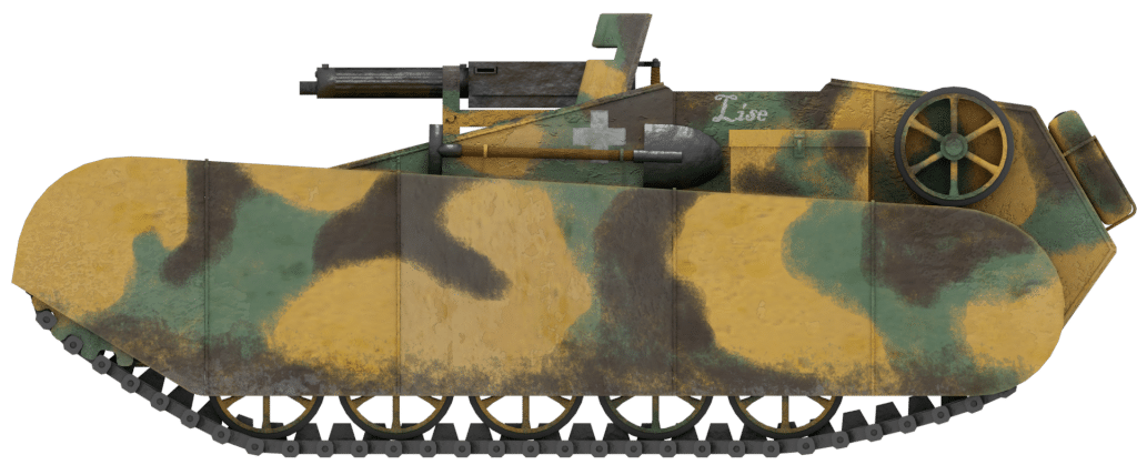
What-if illustration of the Borgward Light Tank by Brian Gaydos, Funded by our Patreon Campaign.
One Last Appearance – 1940
This light tank cropped back up again, for the final time, in November 1940, with the filing of a patent for a drive system for a fully tracked vehicle. This new system would eliminate the rattling noise associated with tracked drive systems as well as making the whole manufacturing process cheaper and simpler. Here, the track was fitted with raised sections on the interior face, which were gripped by teeth on the drive sprocket. Those teeth on the drive sprocket were to be fitted as rollers or bearings which would rotate as the track passed over them, eliminating much of the squeaking and rattling with a conventional track system.

‘Gleiskettenantrieb für Gleiskettenfahrzeuge’ from German Patent DE724797(C) 1942.
Other Work
This was not Carl Borgward and Co.’s only contribution, before and during World War II, in relation to tank technology by any means. Other work was for fittings, fixtures, and features to be used on other armored vehicles, although some of the outlines of the vehicles illustrating those ideas could relate to other, unrealized vehicles.
On the same day (4th November 1937) that Borgward applied for a patent for the protective side skirts (Patent DE734712(C)) on an armored vehicle, he also applied for a patent for a new type of track system for vehicles too. Whilst today there have been numerous attempts, and some vehicles in service use continuous rubber track (also known as ‘band-track’), this was new thinking in 1937 and Borgward applied to protect exactly that idea. The patent was not just for continuous rubber-band trackings but also, more unusually, for a steel track made from a single strip of spring steel. This single-piece steel track was flexible enough to go around the wheels, but provided no gaps through which mud or barbed wire could poke. It could be expected, as it would have a larger footprint on the ground than a track plate with holes in it, to also have a slightly better ground pressure but, as a smooth track, it had no grip. To counteract this, Borgward envisaged using steel shoes bolted through the strip-track (whether it is steel or rubber) to form the grips which would allow it some purchase on soft ground and for crossing obstacles. These would have a recess in them to allow for a rubber pad.

‘Laufband fur Kraftfahrzeuge’ from German Patent DE737703(C) of 1943 showing the continuous band-track (made from rubber or steel) with a ‘shoe’ bolted to it.
In February 1938, Borgward submitted a design (in two patents) for a new type of cupola for tanks and armored cars. This consisted of a large cup-shaped dome covering the cupola and providing coverage over the vision slits or blocks in it. This lid was adjustable, armored and rotatable and was to be fitted with either mechanical or hydraulic lifting means so that it could be elevated partially to provide vision, or fully to allow egress of the tank. In this way, the cupola lid functioned as a hatch which, when elevated, allowed the occupant of the vehicle to raise their head above the lip of the cupola for improved observations whilst providing protection from enemy fire or shrapnel from above. When in the raised position, the occupant could use a reverse periscope arrangement of mirrors on the inner face of the lid and outer face of the cupola to see outwards from behind armor.

‘Panzerturm für Panzerwagen, Tanks o. dgl.’ from German Patent DE736470(C) 1943 (left) and ‘Verdeckte Sichteinrichtung in verstellbaren Hauben von Panzerturmen in Panzerwagen o. dgl.’ from German Patent DE697874(C) 1940 (right).
Other military-related patents filed by Borgward included hydraulic steering for fully tracked vehicles (July 1941), a steering system for half-tracked vehicles (January 1940), and a resilient type of steel track with rubber bushings (August 1938). Further, he patented a dual-engine scheme for steering a fully tracked vehicle by varying drive from a single steering wheel (May 1938).

‘Lenkeinrichtung für Gleiskettenfahrzeuge’ from German Patent DE692794(C) 1940.
Conclusion
The majority of other patents from Borgward were related to cars, engines, bodywork etc. but it is this military vehicle design which is perhaps his most interesting work during the war. Borgward is better known for the Borgward B IV demolition vehicles which bear a superficial resemblance to this light tank but for this design and series of pattern Borgward, again and again, visited the same outline. He would modify it from an offset engine (at the back) in what could have been just an armored vehicle for one man, to a centrally mounted engine (at the back) allowing for a crew of two men.
Borgward considered many of the problems of a light tank, such as the ability to cross trenches and climb obstacles. Further, his design showed the use of torsion bar suspension with five independent wheels, which would certainly have provided excellent performance off-road considering that the predominant form of suspension for light tanks at this time was small coiled springs or leaf-springs on arms.

Borgward B IV demolition vehicle (left) with Goliath demolition device (right). Source: wiki
The problems with the design though are perhaps more obvious. It had no turret which limited fire to a narrow arc at the front and the vehicle lacked a roof (despite Borgward’s later design for a cupola cover), dangerously exposing the crew to shrapnel and enemy fire. With the first submission of this design at the end of 1937, it is surprising that Borgward submitted such an old-fashioned design for a vehicle. Perhaps the closest design to this one is not, in fact, German but Italian. The Carro Veloce 3 (CV.3) series of vehicles started life in 1929 and was in mass production several years before this design. With an encapsulated crew space, the CV.3 offered more protection for the crew than this design and with a double machine-gun mount, significantly more firepower too.
That Italian vehicle (CV.3) had seen service during the Spanish Civil War (1936-1939) alongside the German light tanks like the Panzer I against the Soviet-supplied T-26. The CV.3 was better protected than this Borgward design, the Panzer I had proven superior in fighting ability to the CV.3 as it had a turret, and the Soviet-supplied T-26 light tank had proven superior to both in terms of firepower. Yet despite these shortcomings, Borgward submitted a design for a vehicle worse than all three contemporaries in all areas apart from mobility, for which its advanced suspension would be an advantage. As such then, despite the suspension it is no surprise that the vehicle never entered production or use as improved and enclosed light tanks were already in development for the German Army. The Borgward light tank though is an important stepping stone in German tank evolution, as it marks one of the first light tank designs in Germany to use torsion bar suspension.
Specifications |
|
| Dimensions (L-W-H) | 3.2 x ~2.5 x ~1.0 meter |
| Crew | 2 (possible 1 in 1937) |
| Armament | 1x Machine Gun |
| Armor | N/A, est. 10 – 12mm |
| Total Production | None |
Sources
German Patent DE700020(C) ‘Lenkvorrichtung für Gleiskettenfahrzeuge mittels Lenkbremsen’ filed 27th October 1937. Accepted 14th November 1940. Published 11th December 1940.
German Patent DE720049(C) ‘Drehstababfederung für Lenker von unabhanging gefuhrten Radern von Kraftfahrzeugen’ filed 27th October 1937. Accepted 26th March 1942. Published 22nd April 1942.
German Patent DE719046(C) ‘Militarischen Zwecken dienendes Vollgleiskettenkraftfahrzeug, insbesondere Tank’ filed 27th October 1937. Accepted 5th March 1942. Published 27th March 1942.
German Patent DE718663(C) ‘Schutzchild und Sehschlitzanordung für Panzerwagen’ filed 2nd November 1937. Accepted 26th February 1942. Published 18th March 1942.
German Patent DE734712(C) ‘Schutzeinrichtung für die Gliesketten von Kampfwagen’ filed 4th November 1937. Accepted 25th March 1943. Published 22nd April 1943.
German Patent DE737703(C) ‘Laufband fur Kraftfahrzeuge’ filed 4th November 1937. Accepted 10th June 1943. Published 19th October 1943.
German Patent DE736470(C) ‘Panzerturm für Panzerwagen, Tanks o. dgl.’ filed 6th February 1938. Accepted 6th May 1943. Published 19th June 1943.
German Patent DE697874(C) ‘Verdeckte Sichteinrichtung in verstellbaren Hauben von Panzerturmen in Panzerwagen o. dgl.’ filed 6th February 1938. Accepted 26th September 1940. Published 25th October 1940.
German Patent DE687038(C) ‘Halbgleiskettenfahrzeug’ filed 22nd March 1938. Accepted 21st December 1939. Published 20th January 1940.
German Patent DE692794(C) ‘Lenkeinrichtung für Gleiskettenfahrzeuge’ filed 12th May 1938. Accepted 30th May 1940. Published 26th June 1940.
German Patent DE719862(C) ‘Gleiskette für Gleiskettenfarhzeuge’ filed 18th August 1938. Accepted 26th March 1942. Published 17th April 1942.
German Patent DE734330(C) ‘Lenkvorrichtung für Halbgleiskettenfahrzeuge’ filed 25th January 1940. Accepted 18th March 1943. Published 14th April 1943.
German Patent DE724797(C) ‘Gleiskettenantrieb für Gleiskettenfahrzeuge’ filed 22nd November 1940. Accepted 23rd July 1942. Published 5th September 1942.
German Patent DE734331(C) ‘Einrichtung zur Lenkung von Gleiskettenfahrzeuge’ filed 13th July 1941. Accepted 18th March 1943. Published 14th April 1943.
2 replies on “Borgward Light Tank”
Did Borgward plan on leasing their patents to other tank manufacturers when they built tanks?
Companies regularly do that with patents. However, these patents were probably never used.